
Car Roof Magnetic Mounts: Dynamic Wind Load, Thin Sheet Metal (0.6–0.8mm) Saturation & Highway Sourcing Guide
Compare car roof magnetic mounts for wind load, thin-steel saturation, peel and paint compatibility. Use the worked example and send a vehicle-specific RFQ.
2026/11/01
Car roof magnetic mounts must be selected from installed retention data, not catalog pull ratings alone. A normal breakaway rating in kilogram-force (kgf) is not a payload rating, an allowable shear load or a safe highway speed. Thin steel, protective coatings, roof curvature and aerodynamic moments all change the installation.
Published and reviewed: 2026-11-01. Publisher: CoatedMagnets. This engineering and sourcing guide is for fleet upfitters, sign makers, sensor installers and procurement teams worldwide. The 0.6–0.8 mm thickness range is a screening scenario for a verified ferromagnetic steel roof, not a specification for every vehicle. Aluminum, glass and composite roofs require a different attachment system. Confirm the vehicle’s roof material, allowable loads and mounting instructions first.
Evidence and limits: The equations and worked example below are reproducible calculations with explicitly assumed inputs. They are not vehicle tests, measured product performance, customer case studies or road-use approval. Roof-specific retention, aerodynamic coefficients and coating compatibility remain test inputs. Requirements differ by vehicle, equipment and jurisdiction.
Before ordering samples: Send the vehicle model, roof construction, accessory dimensions and operating envelope for an RFQ review. Include the drawing and required test evidence, rather than asking only for a stronger magnet.
The Highway Procurement Trap: Catalog Pull Is Not Installed Capacity
Consider a hypothetical 6.5 kg rooftop sign held by two magnets labeled 40 kgf each. Their combined reference pull is approximately 784 N, while the payload weight is approximately 64 N. Dividing those numbers gives an apparent ratio above 12, but it compares different quantities and says nothing about sliding or peeling.
Ask the supplier how its rating was obtained: steel grade and thickness, plate size, coating, temperature, pull direction, test rate and whether the finished rubber foot was included. K&J’s steel-thickness article illustrates why bare-magnet normal-pull results depend on the target plate; those results cannot be copied to an unrelated coated-pot assembly.
For a moving vehicle, evaluate at least three separate failure modes:
- Sliding: In-plane wind and inertial loads exceed the available interface friction.
- Lift-off: Upward force exceeds installed magnetic retention plus the relevant downward loads.
- Peeling / overturning: A moment unloads one foot or edge before the complete array reaches its nominal pull limit.
Compare application-specific options in the car roof magnets catalogue, magnetic car roof sign guide, roof light mounting guide, magnetic antenna mount guide and magnetic camera mount guide. A catalogue entry does not establish suitability for a particular vehicle or speed.
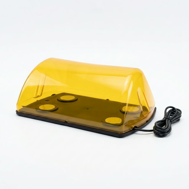
Product illustration of a rooftop sign. The image does not establish magnet force, paint compatibility or road-use suitability.
1. Mechanics of Vehicle Rooftop Magnetic Retention
Draw a free-body diagram of the entire accessory and bracket, with the center of gravity and aerodynamic center of pressure located relative to the feet. Include:
- Weight and vertical acceleration, which change contact pressure.
- Drag, side force and lift at the relevant relative airflow and yaw angle.
- Inertial loads from braking, acceleration and cornering.
- Pitch, roll and yaw moments, including offset lift and cable loads where relevant.
- Roof-panel flex, frame compliance, foot articulation and unequal contact.
The schematic shows one drag direction: the leading feet unload while the trailing feet gain compression. Other wind or acceleration directions can reverse the loaded edge. Dimensions and flux paths are illustrative, not measured field results.
Aerodynamic Force Vectors, Peeling Leverage, and Thin-Sheet Magnetic Flux Leakage
2. Magnetic Circuit Saturation on Thin Automotive Sheet Metal
A pot magnet uses its steel cup and the target sheet as parts of a magnetic return path. A thin sheet can constrain that path, allowing more leakage and reducing normal pull. The effect depends on pole geometry, steel properties, panel size, coatings and gaps. Thickness alone cannot determine a saturation state or a usable force.
The K&J steel-thickness reference reports geometry-specific behavior for bare magnets and explicitly calls for prototyping. It provides no universal 0.7 mm derating factor for rubber-coated pot magnets. Increasing grade, diameter or magnet count therefore requires new installed measurements.
Use the following test-planning matrix, not a force-retention lookup table. Coupon thicknesses are proposed comparison points, not vehicle-model specifications; record thickness in millimeters because gauge conventions vary.
| Steel thickness / condition | Purpose in a qualification plan | Evidence to request | What it cannot establish alone |
|---|---|---|---|
| 0.50 mm coupon | Explore a thinner-sheet sensitivity case | Normal pull and panel deformation for the finished foot | Suitability for any production vehicle |
| 0.60 mm coupon | Lower end of the article’s roof scenario | Repeat pull tests with the specified steel and paint | A generic retained-pull percentage |
| 0.70 mm coupon | Compare candidate pole geometries | Pull and onset-of-slip results with the actual rubber | A catalogue-to-road conversion factor |
| 0.80 mm coupon | Upper end of the roof scenario | Same test method and conditioning as thinner coupons | Proof that the panel cannot saturate |
| 1.00 mm coupon | Assess thickness sensitivity | Matched tests without changing compound or contact area | Interchangeability with a thinner roof |
| 1.50 mm coupon | Explore a thicker return path | Pull versus thickness for the exact assembly | A universal saturation threshold |
| Supplier reference plate | Reproduce the catalogue baseline | Actual grade, dimensions, thickness and test method | Installed capacity on painted sheet |
| Actual curved vehicle roof | Evaluate the complete bracket and feet | Pull, sliding, peel, panel damage and environmental results | Approval outside the tested configuration |
Do not multiply separate “sheet” and “gap” factors unless their combined use has been validated. A rubber-coated product’s catalogue rating may already include its boot; counting that thickness again can duplicate a derating. Keep the measured installed retention as the preferred calculation input.
3. Aerodynamic Drag and Lift at Highway Speeds
For preliminary screening, use the NASA drag equation:
q = 0.5 × rho × v²                 dynamic pressure, Pa
Drag = q × Cd × A_frontal          force, N
Lift = q × CL × A_plan             force, N (upward positive)
Use air density rho in kg/m³, relative airspeed v in m/s and areas in m². The coefficient and reference area must match the tested convention. The example density of 1.225 kg/m³ represents a chosen reference condition; adjust it for the application. Obtain coefficients for the actual accessory, vehicle location and yaw range rather than assigning them from a product name. Lift may change sign with geometry and airflow.
The following values are calculated, not wind-tunnel measurements. Inputs are rho = 1.225 kg/m³, Cd = 0.85 and A_frontal = 0.12 m². The final column is required net normal contact force for drag alone with assumed friction mu = 0.50 and screening factor SF = 3.0: N_required = SF × Drag / mu. It excludes lift, inertia, moments and contamination; it is not the required catalogue pull rating.
| Relative airspeed (km/h) | Relative airspeed (mph) | v (m/s) | q (Pa) | Drag (N) | Required net normal force, drag only (N) |
|---|---|---|---|---|---|
| 60 | 37.3 | 16.67 | 170.1 | 17.4 | 104.1 |
| 80 | 49.7 | 22.22 | 302.5 | 30.9 | 185.1 |
| 100 | 62.1 | 27.78 | 472.6 | 48.2 | 289.2 |
| 120 | 74.6 | 33.33 | 680.6 | 69.4 | 416.5 |
| 130 | 80.8 | 36.11 | 798.7 | 81.5 | 488.8 |
| 140 | 87.0 | 38.89 | 926.3 | 94.5 | 566.9 |
| 160 | 99.4 | 44.44 | 1209.9 | 123.4 | 740.4 |
Doubling airspeed quadruples this simplified drag estimate. A headwind can be added along the travel axis; a crosswind must be combined as a vector, with the resulting yaw angle considered. For example, 120 km/h travel and a perpendicular 30 km/h wind give about 123.7 km/h resultant airflow, not 150 km/h. Local flow over the vehicle can differ from that free-stream estimate.
4. Multi-Pot Footprint Spacing vs. Single Large Magnet
A horizontal drag force acting above the roof creates a moment: M_drag = Drag × z_cp, where z_cp is the center-of-pressure height. A wider support pitch can reduce the extra normal reaction needed to resist the same moment.
For an ideal rigid, symmetric four-foot frame with two feet in each row, row separation L and centered vertical loads:
Change in row reaction = M / L
Change per foot in that row = M / (2 × L)
These are simplified reaction changes, not the total tensile demand or a guaranteed peel capacity. Add lift eccentricity and inertial moments, and check both pitch and roll. A compliant frame, uneven roof or foot losing contact invalidates equal sharing. A single central base needs its own moment test; four small feet do not automatically outperform a properly qualified single-base design.
Once an edge lifts, the increased magnetic gap can further reduce retention and encourage progressive detachment. There is no universal inverse-square or exponential pull-versus-gap law for these assemblies. Request measured gap and peel curves for the exact magnetic circuit.
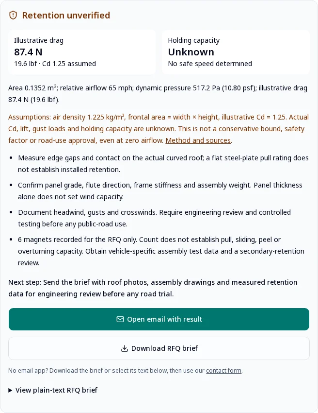
RFQ screening interface illustration: retention is explicitly unverified. These are separate software example inputs, not the worked example below or a physical mount test.
Need to compare suppliers? Send the same roof and bracket specification to request comparable installed-force evidence. Include wet conditions and per-foot loading so that different catalogue test methods do not determine the purchase decision.
5. Automotive Clearcoat Protection: Compound-Level Qualification
A protective boot can reduce direct metal contact, but grit, sliding, trapped moisture, heat and chemical incompatibility can still damage paint. A polymer family or Shore A value cannot establish a friction coefficient, a non-staining guarantee or a service life.
Use this qualitative sourcing matrix to choose samples for testing. It contains no measured comparative performance claims.
| Candidate material | Why consider it | Questions for the compound supplier | Required finished-foot checks |
|---|---|---|---|
| TPV | Flexible thermoplastic processing | Exact grade, oils, additives and weathering data | Hot-contact staining, wet friction and creep |
| Cross-linked EPDM | Candidate for outdoor exposure | Cure system, fillers, process oils and traceability | Paint transfer, abrasion and compression set |
| TPU | Candidate where abrasion matters | Polyester/polyether chemistry and hydrolysis data | Moisture aging, staining and cold flexibility |
| Silicone rubber | Candidate for temperature exposure | Post-cure, extractables and tear resistance | Oil transfer, tearing and wet sliding |
| Flexible PVC | Easily processed soft coating | Plasticizer identity, migration and heat-aging data | Clearcoat compatibility and hardening |
| NBR | Candidate where oil exposure matters | Weathering package, processing oils and color transfer | UV/ozone aging and actual paint contact |
Specify representative OEM and repaired clearcoat panels, contact pressure, dwell time, temperature, moisture and acceptance limits for staining, gloss change, softening and scratches. A volatile-loss or plasticizer-migration test alone does not certify compatibility with automotive paint. Agree the finished-interface test with the vehicle or paint specialist.
For installation instructions, require clean, dry contact surfaces, removal rather than dragging, and an inspection/removal interval agreed with the equipment and vehicle manufacturers. Test rain, dust and repeated installation separately from clean, dry laboratory pull.
6. Vehicle Roof Curvature and Mechanical Articulation
Measure the actual contact location rather than assuming a universal roof crown radius. For a circular roof section with radius R and foot diameter d, the geometric sagitta is:
s = R - sqrt(R² - (d/2)²) ≈ d² / (8 × R)For an assumed 88 mm rigid flat foot and 1,800 mm local radius, s ≈ 0.54 mm. This shows the scale of the geometric mismatch; it does not determine a force reduction. A flexible roof, compressible boot and mounting angle change the actual gap distribution.
Swivel studs or compliant bushings can help align the foot angle. They cannot flatten the local curved sheet or guarantee full contact. Confirm articulation travel, cable movement, bracket stiffness, residual gaps and local panel stress, then test the assembled mount. Excessive compliance can increase motion and fatigue.
7. Worked Engineering Calculation: Screening a Mount for a 120 km/h Requirement
Hypothetical example only: This is a spreadsheet-style load screen, not a tested light bar or a safe-speed recommendation. All coefficients, installed pull and friction values below are assumptions. The purpose is to show why a seemingly large pull rating can still fail a procurement criterion.
Application Design Parameters
- Requested vehicle speed: 120 km/h; assumed direct headwind: 20 km/h.
- Design relative airflow: 140 km/h, or 38.889 m/s; density: 1.225 kg/m³.
- Frontal area: 0.14 m²; assumed
Cd = 0.65. - Plan area: 0.30 m²; assumed upward
CL = 0.35. - Payload plus bracket mass: 8.5 kg;
g = 9.81 m/s²; weight: 83.4 N. - Four-foot symmetric frame; longitudinal pitch: 0.35 m.
- Assumed center-of-pressure and center-of-gravity heights: both 0.14 m.
- Assumed installed magnetic pull: 80.3 N per finished foot on the intended 0.75 mm painted steel; no measurement is claimed.
- Assumed interface friction:
mu = 0.50; assumed acceleration envelope:0.8 g. - Illustrative procurement screening target:
SF = 3.0, chosen for this example, not attributed to a standard.
Step 1: Calculate Aerodynamic and Inertial Loads
q = 0.5 × 1.225 × (140/3.6)² = 926.3 Pa
Drag = q × 0.65 × 0.14 ≈ 84.3 N
Lift = q × 0.35 × 0.30 ≈ 97.3 N
Inertial load = 8.5 × 0.8 × 9.81 ≈ 66.7 N
For this preliminary envelope, conservatively sum the horizontal magnitudes: H = 84.3 + 66.7 = 151.0 N. Drag and braking inertia need not point in the same direction; signed load cases must replace this envelope in the final design. Side gusts and vertical acceleration are not resolved here.
Step 2: Evaluate Sliding
Installed magnetic pull total = 4 × 80.3 = 321.2 N
Net normal contact force = 321.2 + 83.4 - 97.3 = 307.3 N
Available friction = 0.50 × 307.3 = 153.7 N
Sliding screening factor = 153.7 / 151.0 ≈ 1.02
The candidate fails the example’s 3.0 screening target. Dry, static friction is itself insufficient evidence for wet, vibrating service.
Step 3: Check the Simplified Front-Row Reaction
Using a magnitude envelope for both horizontal moments, and assuming centered lift and weight:
M_envelope = 84.3 × 0.14 + 66.7 × 0.14 ≈ 21.1 N·m
Extra unloading per front foot = 21.1 / (2 × 0.35) ≈ 30.2 N
Remaining contact per front foot = 307.3/4 - 30.2 ≈ 46.6 N
Positive contact in this idealized model does not demonstrate peel resistance, fatigue life or a margin against vertical shock. Offset lift, roll, roof deflection and unequal foot stiffness require further load cases and physical tests.
Step 4: Compare a Higher Installed-Pull Candidate
Suppose a different candidate provides an assumed 145 N per foot under the same installed conditions. Total magnetic pull would be 580 N, net contact approximately 566 N and friction approximately 283 N. Its sliding factor is 283 / 151 ≈ 1.87: it still fails the same 3.0 target. A larger catalogue magnet cannot be approved from this assumption.
For that target and these rounded assumptions, required installed magnetic pull is:
Required net contact = 3.0 × 151.0 / 0.50 = 906.0 N
Required magnetic pull total = 906.0 + 97.3 - 83.4 = 919.9 N
Equal-share arithmetic = 919.9 / 4 ≈ 230 N per foot
The 230 N figure is an input for supplier discussion, not a product rating or selection. Reducing frontal area or height, using a qualified mechanical attachment, or redesigning the support may be preferable. Do not extrapolate the calculation into highway certification.
8. Sourcing & Qualification Checklist for Vehicle Magnetic Mounts
Use this ten-point checklist to make bids comparable. Acceptance limits must be agreed by the responsible vehicle/equipment engineer for the application; the table does not prescribe a universal standard.
| Verification item | RFQ / acceptance evidence | Decision if missing |
|---|---|---|
| 1. Roof construction | Vehicle model/year, steel grade and thickness, curvature, paint and allowed roof load | Confirm construction before choosing magnetic attachment |
| 2. Catalogue baseline | Reference plate, test direction, finished-foot condition, temperature and test method | Do not convert kgf into payload capacity |
| 3. Installed retention | Repeated normal-pull, sliding and peel tests on representative roof assemblies, including variability | Keep holding capacity unverified |
| 4. Aerodynamic envelope | Accessory dimensions, coefficient/area conventions, yaw, gusts and center-of-pressure location | Do not assign a safe speed |
| 5. Compound and paint | Traceable compound, finished-interface staining, wet/dry friction and aging results | Withhold paint-compatibility claims |
| 6. Footprint and articulation | Per-foot reactions, frame stiffness, roof deflection, gaps and swivel limits | Redesign or test incomplete contact |
| 7. Fasteners and core retention | Stud/thread specifications, assembly torque, joint retention, fatigue and core-to-cup retention evidence | Require proof of the complete load path |
| 8. Environment | Agreed temperature range, water/salt/UV exposure, corrosion criterion and post-aging retention | Do not infer field life from one laboratory exposure |
| 9. Complete-system tests | Combined load cases, vibration/shock plan, vehicle/equipment instructions and applicable local requirements | Do not release solely on static calculations |
| 10. Secondary retention and service | Engineer-reviewed secondary attachment, installation checks, inspection interval and removal procedure | Resolve failure consequences before road use |
Frequently Asked Questions
Why can a high-pull-rated magnet detach from a car roof?
Catalog pull is a normal breakaway force under the supplier’s reference conditions. Thin steel, paint, rubber, curvature, lift and overturning can reduce installed retention. Obtain pull, sliding and peel tests on the actual roof assembly; a kilogram-force rating does not establish payload capacity or safe speed.
How does 0.6–0.8 mm roof steel affect magnetic holding force?
Thin ferromagnetic sheet can limit the magnetic return path and reduce pull. The reduction depends on the magnet circuit, steel grade, thickness and gaps. There is no universal retention percentage for 0.7 mm steel; require assembly-specific measurements rather than transferring bare-magnet calculator results to coated pots.
Is a four-point magnetic array always safer than one large magnet?
A wider footprint can reduce the extra tensile reaction needed to resist a given overturning moment. Four feet do not guarantee equal load sharing or road safety. Check frame stiffness, individual contact, roof flex, load direction and the weakest foot using the complete assembly.
Which rubber coating is safe for automotive paint?
No polymer family guarantees paint compatibility. Consider TPV, EPDM or another documented compound, then test the finished foot against representative OEM and repaired clearcoats under heat, moisture and movement. Request compound identity, staining results and wet friction data; remove trapped grit before installation.
What safety factor makes a magnetic roof mount highway-certified?
A calculated safety factor alone does not certify a mount or establish a safe speed. This guide uses 3.0 as an illustrative procurement screening target, not a requirement attributed to a standard. Vehicle-specific testing, manufacturer instructions and applicable local requirements determine acceptance.
Can swivel joints make flat magnets fit a curved vehicle roof?
Swivel joints can correct foot angle but cannot make a rigid flat face conform to local roof curvature. Measure the residual gap and panel deflection, then test pull and peel with the intended bracket, coating and roof. Added compliance must also be checked for movement and fatigue.
Technical Summary & Sourcing Next Steps
The purchase decision requires three separate evidence sets: installed magnetic retention, aerodynamic and inertial load cases, and finished-interface durability and paint compatibility. Keep unknowns visible in the RFQ. Magnet count, polymer name and a catalogue kgf rating cannot fill those gaps.
Send your vehicle model, roof photos, accessory drawing, speed/wind requirement and available test records to CoatedMagnets to define the next sample and evidence request. A quotation or calculation does not replace application approval by the responsible engineer.
Sources & Engineering References
Source links and their claim boundaries were reviewed on 2026-11-01. None supplies a certification or a universal coated-magnet force table.
- NASA Glenn Research Center — Drag Equation. Supports the aerodynamic equation and the need to match coefficient with reference area. It does not provide coefficients for the rooftop products in this guide.
- K&J Magnetics — Calculating Steel Thickness for Neodymium Magnets. Manufacturer explanation and geometry-specific bare-magnet examples supporting thickness sensitivity. Its data does not establish retention percentages for coated pot assemblies or vehicles.
- K&J Magnetics — Steel Plate Thickness Calculator. Official calculator linked from the thickness article; a reference for bare-magnet estimates with stated application limits, not a rubber-coated-pot or road-use qualification tool.