
High-Temperature Mounting Magnets: Thermal Demagnetization Limits, CTE Mismatch & Pot Assembly Sourcing Guide
Compare high-temperature mounting magnets by grade, hot pull force, CTE mismatch and potting limits. Use the RFQ checklist to specify and qualify your assembly.
2026/10/28
High-temperature mounting magnets cannot be sourced from a single catalog temperature rating. A datasheet listing "Maximum Operating Temperature: 150°C" does not mean the finished assembly will retain its rated pull force, resist internal shear stress, or survive thermal cycling inside your equipment.
Published and reviewed: 2026-10-28. Publisher: CoatedMagnets. This English-language guide serves engineers and procurement teams sourcing coated magnet assemblies globally for roughly 80°C–250°C applications. It combines manufacturer reference data with a sourcing and qualification framework; it does not report CoatedMagnets laboratory tests or customer results. Grade limits describe the core material, not an approved working load or service life for a finished mount. Confirm local application requirements and the complete assembly's limits before release.
The Thermal Mounting Paradox: Why "150°C-Rated" Magnets Fail at 130°C
Illustrative failure scenario, not a measured case study: an automation engineer selects a pot magnet with an SH-grade NdFeB core, listed at 150°C, to hold a sensor bracket in a 130°C paint-curing oven.
If that bracket slips or the potting cracks, the temperature label alone cannot explain the failure. Check hot holding force, the actual coating gap, detachment conditions and bondline integrity separately; do not diagnose a percentage of permanent demagnetization without before-and-after measurements.
+---------------------------------------------------------------------------------------+
|                              THE THERMAL PROCUREMENT TRAP                             |
|                                                                                       |
|   Catalog Assumption:  N38SH Core Rated to 150°C  ==>  Safe at 130°C Bake Cycle?      |
|                                                                                       |
|   Engineering Reality:                                                                |
|   1. Paint & Air Gap              -->  Changes pull force and the circuit load line  |
|   2. Hot Detachment Off Conveyor  -->  May cross the grade's hot demagnetization knee |
|   3. Directional CTE Mismatch     -->  Unequal expansion strains the potting bondline |
|                                                                                       |
|   Check separately: reversible loss, permanent flux loss, and mechanical damage      |
+---------------------------------------------------------------------------------------+
This failure happens because magnetic holding assemblies are coupled multi-material mechanical systems, not isolated alloy blocks. Safe high-temperature operation requires balancing three independent engineering thresholds:
- The Magnetic Operating Point (Pc): The circuit permeance coefficient determined by steel cup geometry, target thickness, and air gap.
- The Resin and Coating Boundary: Glass transition temperature (Tg), adhesion, creep and aging of the encapsulation polymer or adhesive.
- The Differential CTE Tensor: The thermal expansion mismatch between the anisotropic sintered magnet core, the isotropic low-carbon steel cup, and the potting matrix.
Quick sourcing rule: Never approve a high-temperature magnet drawing without defining: (a) operating air gap, (b) peak temperature and dwell duration, (c) whether detachment occurs hot or cold, and (d) thermal cycle frequency. Submit your operating temperature profile and dimensional envelope for an engineering review before finalizing prototype tooling.
For standard ambient and moderate-temperature mounting hardware, review our rubber-coated pot magnet sourcing guide and coating comparison guide. To evaluate specific high-heat assemblies, inspect our high-temperature mounting magnet product specifications and magnetic fixture base catalogue.
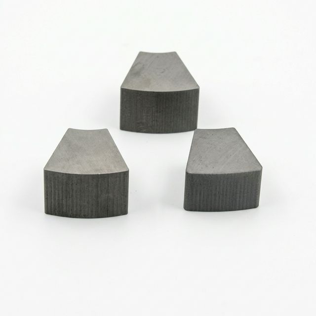
Catalogue illustration of core segments; this image does not show a finished pot assembly or establish an alloy grade or thermal rating.
1. Demagnetization Mechanics: Reversible, Irreversible, and Structural Losses
Permanent magnets do not simply stop working when heated; they undergo three distinct tiers of magnetic degradation. Understanding these mechanisms is essential for establishing realistic engineering safety margins.
1.1 Reversible Loss and Coercivity Margin
Remanence falls as temperature rises. Arnold's NdFeB grade table lists a typical remanence coefficient of -0.12%/°C for its basic grades. Its RECOMA SmCo table lists -0.035%/K for many 2:17 grades. A one-degree Celsius change equals a one-kelvin change.
These are material coefficients, not pull-force derating factors. Holding force also depends on contact geometry, steel saturation, gap and load direction. Use the coefficient only within its stated temperature interval; obtain hot curves rather than extending a room-temperature linear estimate to the full service range. A reversible magnetic change recovers on cooling if the magnet has avoided irreversible loss and the assembly has not moved or degraded.
Intrinsic coercivity also decreases with temperature, reducing resistance to demagnetization. Its coefficient describes a different property from remanence and cannot establish the finished assembly's force retention.
1.2 Irreversible Demagnetization (The Knee of the Second Quadrant)
Irreversible loss can occur when the circuit load line places the hot operating point beyond the knee of the grade's demagnetization curve. Review the normal B–H and intrinsic J–H curves at temperature; intrinsic coercivity alone does not locate the safe operating point.
When the operating point falls below this knee:
- Some magnetic domains reverse, reducing the net magnetization.
- When cooled back to room temperature, the lost flux does not return.
- Supplier remagnetization may restore magnetic output if the material is intact; the required field depends on the grade and geometry. It cannot repair a damaged coating, core or bondline.
1.3 Curie Temperature and Physical Damage Are Different Limits
At the Curie temperature, spontaneous magnetic ordering is lost. This is distinct from chemical or mechanical damage and is not a usable service-temperature specification. A mounting assembly can fail far below that point through oxidation, cracked magnet material, adhesive softening or loss of retention. Those physical changes will not be repaired by cooling or remagnetizing. No universal oxidation threshold applies independently of atmosphere, coating and exposure time.
2. Circuit Load Line & The Pot Assembly Effect: Why Hot Detachment Matters
In SI units, the positive permeance coefficient is Pc = B / (μ₀ × |H|) for a second-quadrant operating point. A thin magnet in an open circuit can have a lower operating permeance than a well-designed steel-backed assembly in contact with its target. There is no single value for all pot magnets: core shape, cup saturation, target material, target thickness and gap matter. The Arnold NdFeB catalogue supplies grade-specific curves with load lines for this assessment.
Diagram scope: the following curves and arrows are qualitative schematics, not supplier test data or a simulation of a particular grade. Scroll horizontally on a narrow screen. Numerical CTE assumptions are explained in the worked example below.
Schematic: Load-Line Shift & Multi-Material Thermal Expansion
What the Steel Cup Changes
The cup provides a ferromagnetic return path, but its benefit depends on the whole circuit. Request an analysis of both contact with the thinnest permitted target and the largest operating gap, including a fully detached state when relevant. Do not substitute a fixed minimum steel thickness or a universal Pc threshold for that analysis.
Qualify Hot Detachment Separately
Opening the circuit while hot may move the operating point past the knee. Whether this causes irreversible loss, and how much, depends on the grade and geometry; a temperature label cannot predict the result. Higher-coercivity NdFeB or SmCo may be candidates, but neither guarantees safe hot release.
Engineering protocol: require hot demagnetization curves and an assembly-level release test at the worst detachment temperature. Record pull force before heating, while hot and after cooling in the same fixture. If the application cannot tolerate a release, specify independent mechanical retention rather than relying solely on catalog pull force.
3. Multi-Material CTE Mismatch in Pot Assemblies
Even with adequate magnetic margin, unequal expansion can load the core and bondline. Sintered NdFeB is an anisotropic intermetallic material; it is not a ceramic. Its expansion depends on the direction relative to magnetization.
3.1 Use Directional, Grade-Specific Expansion Data
For example, the N35 sheet in Arnold's NdFeB catalogue, PDF page 4 gives typical CTE values of +7 ppm/K parallel and -1 ppm/K perpendicular to alignment over 20°C–200°C. These are reference values, not a specification for every NdFeB grade. Obtain directional data for the selected core and temperature interval; use the cured compound's CTE and modulus for the potting.
3.2 Worked Example: Diametral Mismatch Is Not Radial Gap
Screening assumptions: an axially magnetized core and cup bore each have a nominal diameter of 50 mm; the steel CTE is assumed to be +12 ppm/K, the core's transverse CTE is -1 ppm/K, and heating is from 20°C to 150°C (a 130 K rise). Use free expansion and constant coefficients; ignore adhesive restraint and the initial clearance for this first estimate.
- Cup diameter change:
50 × 12 × 10⁻⁶ × 130 = +0.078 mm. - Core diameter change:
50 × (-1) × 10⁻⁶ × 130 = -0.0065 mm. - Diametral clearance change:
0.078 - (-0.0065) = 0.0845 mm. - Radial bondline opening on each side: approximately 0.042 mm (42 µm), half the diametral change.
This reproducible calculation identifies a displacement demand; it is not measured damage or a stress prediction. Actual bond stress also depends on resin modulus at temperature, cure shrinkage, geometry, initial clearance and restraint. Confirm these inputs before choosing a bondline thickness.
3.3 Inspect Three Failure Paths
- Bondline separation: unequal movement can load the adhesive in shear and peel. Check for cracks, debonding and core movement after cycling.
- Core cracking: both NdFeB and SmCo are brittle. Interference, cure shrinkage and cooling from the cure temperature can create local stresses; qualify the actual retention geometry.
- Loss of environmental protection: a damaged coating or seal may admit moisture and chemicals. Inspect corrosion and seal condition as well as pull force. A potted assembly is not automatically hermetic.
4. Engineering Comparison: Core Magnet Alloys Under Thermal Stress
The material values below come from Arnold's NdFeB grade table and RECOMA grade table. The final column is our sourcing guidance. These are named manufacturer examples, not interchangeable grades or CoatedMagnets assembly ratings.
| Core grade example | Listed maximum material temperature | Room-temperature HcJ* | Qualification question |
|---|---|---|---|
| NdFeB N42 | 80°C | 12 kOe | Is an ordinary grade excluded by the actual hot duty? |
| NdFeB N52 | 60°C | 11 kOe | Does choosing higher room-temperature output sacrifice thermal margin? |
| NdFeB N38SH | 150°C | 20 kOe | Does the hot curve cover both contact and release states? |
| NdFeB N35UH | 180°C | 25 kOe | Is worst-gap hot holding force adequate? |
| NdFeB N33EH | 200°C | 30 kOe | Have coating, adhesive and retention been qualified together? |
| NdFeB N30AH | 220°C | 34 kOe | Does the supplier confirm this exact grade and geometry? |
| SmCo RECOMA 28 | 350°C | 25 kOe | Are core brittleness, hot curves and retention addressed? |
| SmCo RECOMA 35E | 300°C | 23 kOe | Does its higher output justify the specific grade choice? |
HcJ values for NdFeB are listed minima; the RECOMA page describes its values as typical. Compare complete hot curves rather than room-temperature HcJ alone. No row approves operation of a finished mount at the listed maximum. Obtain current quotes for equivalent geometry and test requirements; fixed cost multipliers are not reliable across grades or suppliers.
5. Potting, Encapsulation & Adhesive Systems for Thermal Pot Magnets
A core's temperature capability does not establish an adhesive or overmold rating. Select the exact compound and cure schedule, then test adhesion and creep in the real assembly. Tg is a transition in polymer behavior, not a universal continuous-service limit; elastomers also have a Tg, often below their working range.
| Potting / coating candidate | Evidence to request | Assembly-specific trade-off |
|---|---|---|
| General-purpose epoxy | Exact formulation, cure and hot lap-shear/creep data | A room-temperature strength value cannot approve hot retention. |
| Filled high-temperature epoxy | Cured Tg, directional CTE if relevant, modulus and aging data | Lower expansion may accompany greater stiffness and bond stress. |
| Silicone elastomer | Temperature/time rating, adhesion and fluid-immersion results | Compliance may accommodate movement; verify mechanical retention. |
| FKM overmold | Compound and cure designation, compression set and media compatibility | Protective thickness adds a magnetic gap; qualify hot friction and pull. |
| Polyurethane overmold | Exact chemistry, hot-water aging and dimensional stability | Abrasion resistance alone does not establish steam or heat suitability. |
| Inorganic cement / ceramic potting | Cure, shrinkage, adhesion, porosity and thermal-cycle results | Check cracking and whether separate core retention is required. |
A concrete datasheet example: Master Bond EP42HT-2 is a two-component epoxy offered for potting, with a stated service range ending at 450°F (about 232°C). That product-specific claim is not a temperature limit for all epoxies or an endorsement for a magnet assembly. Request its full technical data and confirm the selected cure, substrate preparation and aged bond strength.
Engineering Guidelines for Bondline Design
- Choose fillers through compound data: compare cured expansion, modulus and processability rather than prescribing a universal filler percentage.
- Size the bondline from movement and stress: use the directional expansion calculation as an input, then evaluate the actual clearances, temperature-dependent properties and retention geometry. A fixed gap cannot guarantee cycle life.
- Validate surface preparation: agree on cleaning and primer with the adhesive supplier and the magnet coating supplier. Qualify adhesion on the production finish before and after thermal and fluid exposure.
Have the core grade but not the potting specification? Send the drawing and thermal duty for a complete assembly review before locking the bill of materials.
6. Sourcing & Quality Audit Checklist for High-Temperature RFQs
Use this 10-point checklist when drafting procurement specifications or auditing supplier qualification samples for high-temperature applications.
- 1. Complete Thermal Duty Cycle Profile: State the exact baseline operating temperature, maximum peak excursion temperature, dwell time at peak (minutes or hours), ramp rate (°C/minute), and total required design cycle life.
- 2. Detachment Temperature State: State the maximum temperature at which the base will be attached or detached, including maintenance and abnormal operating states.
- 3. Ferromagnetic Substrate Specification: Define target steel grade (e.g., AISI 1018, S235JR), minimum thickness, roughness, curvature and the maximum gap from paint, scale or the magnet coating.
- 4. Operating-Point Verification: Request hot B–H/J–H curves and a supplier load-line or finite-element assessment for worst-gap and detached states. Agree on margin to the knee; do not use one Pc value as universal acceptance.
- 5. Alloy Grade & Coercivity Callout: Specify the manufacturer and full grade designation, room-temperature Br and HcJ tolerances, and hot curves. Confirm lot traceability and any thermal stabilization; suffix conventions alone are insufficient.
- 6. Potting Resin & Coating Specification: Require exact product codes, cure conditions, cured Tg/CTE and modulus where relevant, service-temperature/time limits, and compatibility with the actual finish and fluids.
- 7. Humidity or Steam Qualification: Define the application's temperature, pressure, humidity, chemicals and exposure duration. Agree on corrosion and ingress checks; a mass-change or humidity test alone does not prove hermeticity.
- 8. Thermal Cycling Acceptance: Agree on sample count, ramp rate, hot/cold dwell, cycle count and failure limits against design life. As an illustrative screening plan only, 100 cycles from -40°C to the specified peak with 60-minute dwells and at least 95% recovered room-temperature pull retention may be proposed; this is not a standard or lifetime proof. Also require an absolute minimum hot holding force and no unacceptable cracks or core movement.
- 9. Fastener & Retention Design: Specify hardware material, temperature capability, thread engagement, tightening procedure and corrosion compatibility. Verify loosening, seizure and retention after cycling; select strength class from the design loads.
- 10. Measured Acceptance Report: Require before-exposure, hot and recovered room-temperature pull results with actual temperatures, specimen IDs and uncertainty. Fix the target, gap, pull direction and pull rate. Separately test shear, vibration and release where applicable; state the application's working-load margin.
7. Frequently Asked Questions (FAQ)
Why can a 150°C-rated NdFeB mounting magnet lose holding force in a 130°C paint-bake cycle?
A core grade rating is not a finished-assembly holding-force guarantee. Reversible magnetic loss, a larger gap, adhesive movement or irreversible demagnetization can reduce force. Compare hot and cooled pull tests in the same fixture; temperature alone cannot identify the cause.
What is the difference between reversible flux loss and irreversible thermal demagnetization?
A reversible magnetic change recovers on cooling if the circuit and assembly remain intact. Irreversible loss does not recover on cooling. Supplier remagnetization may restore magnetic output, but it cannot repair cracks, corrosion or a damaged bondline.
How can CTE mismatch between NdFeB and steel damage a pot magnet assembly?
Expansion can differ along and across the magnetization direction. Unequal movement of the core, cup and potting can load the adhesive and brittle core. Use grade-specific directional CTE and cured adhesive properties; a clearance calculation alone does not predict bond stress or cycle life.
When should an engineer compare SmCo with high-temperature NdFeB?
Compare SmCo when the actual duty approaches 180°C–200°C or higher, or when flux stability is important. Select the exact grade using hot curves, geometry, environment and current quotes. Neither a material family nor a temperature label approves the finished assembly.
How should rubber or polyurethane coatings be qualified for high-temperature mounting magnets?
Request the exact compound, cure, temperature/time limits, fluid compatibility and aged adhesion or retention results. Polymer families contain different formulations, so there is no single 80°C–100°C failure threshold for all rubber or polyurethane coatings. Include coating thickness in the magnetic gap.
Can a hot pot magnet be released from a steel fixture inside a curing oven?
Only after the detached circuit and mechanical release have been qualified at that temperature. Opening the gap can reduce permeance and may cause irreversible loss, depending on grade and geometry. Use hot curves and assembly tests; high-coercivity NdFeB or SmCo alone does not guarantee safe hot release.
8. Sources and Industry References
References checked: 2026-10-28. These primary manufacturer sources support material screening. They do not certify CoatedMagnets products or the example qualification plan.
- Arnold Magnetic Technologies: Neodymium Iron Boron Magnets — available grade table. Source for the named NdFeB material temperatures, room-temperature coercivity and remanence coefficient.
- Arnold Magnetic Technologies: Neodymium Iron Boron Magnet Catalog. N35 sheet, PDF page 4 (revision 210607), supplies directional CTE over 20°C–200°C and demagnetization curves; individual grade sheets state their coefficient intervals. The older PDF and current web table can differ: the comparison matrix uses the web table's material ratings.
- Arnold Magnetic Technologies: RECOMA Samarium Cobalt Magnets — grades and properties. Source for the RECOMA examples and typical induction coefficient. Different SmCo grades have different limits.
- Master Bond: EP42HT-2 product information. A specific potting-capable epoxy example with stated cure and service conditions; not a generic polymer-family rating.
Request an Engineering Thermal Review for Your Assembly
Bring the magnetic circuit and material stack into the same RFQ so suppliers can assess the complete mount.
Contact CoatedMagnets Engineering with your application details:
- Peak operating temperature and continuous dwell time
- Permissible air gap and counter-surface steel thickness
- Target pull force required at operating temperature vs room temperature
- Chemical, oil, or washdown fluid exposure
- 2D/3D CAD mounting envelopes or threaded stud constraints
Use these details to discuss NdFeB versus SmCo, potting and retention options with CoatedMagnets, and agree on the sample qualification and acceptance evidence needed before production approval.