
Rubber Coated Pot Magnets: Shear Force vs Direct Pull Force Sourcing Guide
Compare shear force vs direct pull for rubber coated pot magnets. Use a worked example and supplier checklist, then request a review of mounting requirements.
2026/10/26
Rubber coated pot magnets must be sized for the installed load direction. Direct pull is normal to the steel surface; shear acts along it, and an offset bracket also creates a peeling moment. A catalogue pull rating alone cannot establish an acceptable vertical payload.
Published and reviewed: 2026-10-26. Prepared by CoatedMagnets for global OEM buyers, mechanical engineers and sourcing teams. This guide covers preliminary selection on ferromagnetic steel and supplier qualification. The numerical example is hypothetical, not a physical test or an approved working load. Overhead, road-going and personnel-critical assemblies require a separate application assessment.
The Vertical Mounting Paradox: Why High-Pull Magnets Can Slip
Consider an illustrative purchase: a base advertised at 45 kg pull is selected to carry a 9 kg enclosure on a painted vertical panel. Those figures describe different quantities. If the catalogue means 45 kgf, that is about 441 N of breakaway force under its stated test conditions; the enclosure weighs about 88 N. The buyer still needs installed clamping force, friction, bracket offset and dynamic loading before comparing demand with capacity.
Quick sourcing rule: request normal pull, onset-of-slide and offset-bracket test results on the actual panel. Ask what substrate and air gap produced each rating. Send your load direction, panel thickness and bracket drawing for a mounting review if those inputs are not yet defined.
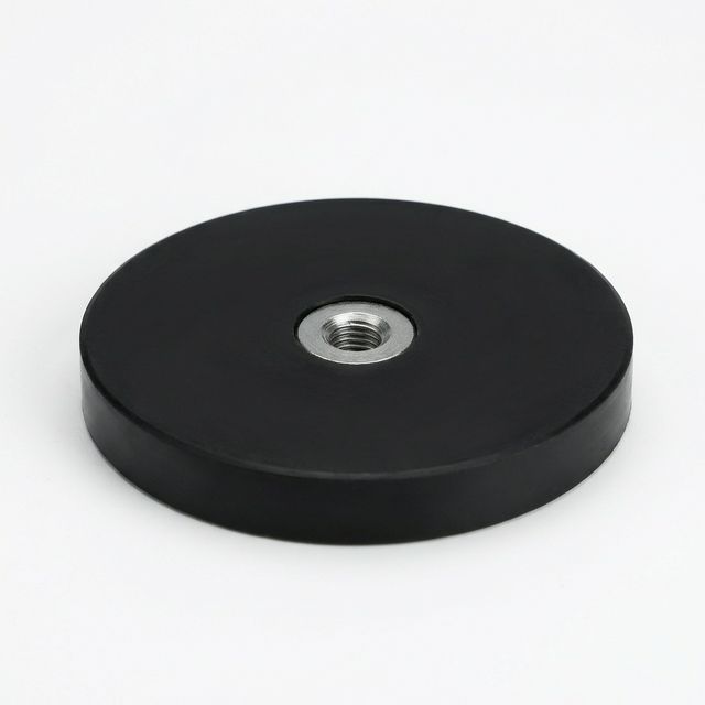
For coating selection, consult our coating comparison guide and rubber vs epoxy coating comparison. For dimensions and connection formats, review the rubber coated pot magnet and male threaded pot magnet pages. A product photo identifies the format, not the internal pole arrangement or a tested capacity.
1. Free-Body Mechanics: Normal Pull Force vs. Lateral Shear Force
The following diagram separates three failure modes. It is a schematic, not a measured load test; the text below provides the same selection logic.
Free-Body Mechanics: Normal Detachment vs. Lateral Sliding vs. Peeling Moment
1.1 The Friction Screening Equation
For a flat mount on a uniform steel surface, a first approximation for the onset of sliding is F_slide ≈ μ_s × N. Here F_slide is force in newtons, μ_s is the measured static friction coefficient of the contacting surfaces, and N is the actual compressive contact force in the installed condition. Magnetic attraction supplies that compression when there is no additional normal load.
A catalogue breakaway result is only a proxy for N when substrate, gap, temperature and loading match. External normal tension, flexible brackets, peel, surface edges and vibration can invalidate this simple model. kg is mass; kgf is force, with 1 kgf ≈ 9.81 N. Request supplier ratings in N with the test setup stated. The MDFA normal breakaway method describes perpendicular detachment, not lateral sliding approval.
1.2 Worked Example: A Vertical Enclosure
These are assumed inputs for arithmetic only, not measured values or recommended design factors:
- Payload mass: 9 kg; gravity load: 9 × 9.81 = 88.3 N.
- Assumed installed clamping force: 300 N; assumed static coefficient: 0.40.
- Estimated onset of sliding: 0.40 × 300 = 120 N.
- Raw static margin: 120 / 88.3 = 1.36, before peel, shock or aging.
- If an engineer chose an illustrative margin of 3 for this particular calculation, the screening load would be 120 / 3 = 40 N, equivalent to about 4.1 kg under gravity. The 9 kg payload exceeds that screening load.
Changing the assumed coefficient to 0.20 reduces the sliding estimate to 60 N, already below the payload weight. This sensitivity is why a measured slip test is more useful than selecting a coefficient from a rubber family name. Replacing either assumption with a catalogue value from another substrate defeats the calculation.
1.3 Cantilever Moment and Peeling
A payload force W acting at an offset L from the wall creates M = W × L, expressed in N·m. The example's 88.3 N payload at a 0.10 m offset creates 8.83 N·m. This moment can lift one edge and reduce magnetic attraction before the assembly reaches its pure-sliding limit.
A rigid-disc estimate sometimes compares this demand with N × D/2, but a real magnetic pressure distribution, compliant jacket and opening gap make that an unreliable acceptance limit. No universal offset-to-diameter rule establishes peel resistance. Evaluate the complete bracket; vertically spaced bases or a mechanical stop may help, but load sharing and retention still require testing.
2. Magnetic Circuit Engineering: The Air-Gap Trade-Off
Rubber adds a non-magnetic gap while protecting the mating finish. Cup-style and multi-pole assemblies have different flux-return paths, so equal outside diameter does not mean equal installed force. The following illustration compares concepts rather than predicting a percentage improvement.
Magnetic Circuit Architecture: Axial Disc vs. Multi-Pole Assembly (Schematic)
2.1 Specify the Complete Gap
The relevant gap includes the jacket, paint, protective films, curvature and imperfect contact. There is no universal coating thickness or percentage pull loss applicable to all magnet geometries. Ask for a force-versus-gap curve for the finished coated assembly. If its rating already includes the jacket, do not apply a second arbitrary rubber derating.
The MDFA method allows breakaway measurements at several controlled gaps. It checks that the test plate is not saturated; it does not establish one minimum plate thickness for every magnet. Record plate material and thickness rather than assuming any thick plate reproduces a vehicle skin.
2.2 Steel Backing and Stray Fields
A ferromagnetic cup or backing plate provides a flux-return path. Its effectiveness depends on geometry, steel properties and the working gap. It does not guarantee zero backside field or compatibility with compasses and other magnetic sensors. Obtain field measurements and the equipment manufacturer's separation guidance when interference matters.
2.3 Multi-Pole Arrays on Thin Sheet
Closer pole spacing can offer shorter flux paths, which may help some thin-sheet applications. It can also increase sensitivity to gaps. Neither complete flux closure in a specified thin sheet nor a fixed advantage over an axial cup follows from the label “multi-pole.” Compare actual pull and slide measurements on the intended steel thickness, coating and curvature, and obtain a supplier cross-section identifying the pole arrangement.
3. Tribology and Elastomer Selection
Friction belongs to the contact system: compound, texture, pressure, surface finish, temperature, dwell time and contamination all matter. Rubber may improve grip while reducing normal attraction; the net result requires testing both effects together.
3.1 TPV, EPDM and Silicone: Ask for the Exact Compound
Treat TPV (including Santoprene grades), EPDM, silicone and polyurethane as candidate material families. A family name alone cannot establish friction, fuel compatibility, UV life or an operating temperature range. Require the compound designation, supplier datasheet and an agreed hardness tolerance. ASTM D2240 describes durometer measurement; a Shore A value is not a coefficient of friction or proof of long-term grip.
For hot service, check the magnet grade, bonding system and insert retention as well as the elastomer. The lowest qualified component limit governs the finished assembly. The linked standard product page lists a -20°C to +80°C range for its standard construction; higher-temperature options need a separate review.
3.2 Validate Surface and Environmental Conditions
- Dry steel: record roughness, flatness and cleaning method; compare like-for-like surfaces.
- Painted or waxed panels: use the actual cured finish and any wax or ceramic treatment; include the coating gap in the magnetic test.
- Wet, oily or dusty service: reproduce the expected contamination in a controlled fixture. Do not assume that a dry result remains valid or that a mechanical stop alone solves every detachment mode.
- Aged or cold service: repeat grip and peel measurements after the specified temperature and exposure cycle. Compound flexibility alone does not prove retained holding force.
ASTM D1894 concerns friction of plastic film and sheeting. A supplier may adapt its concepts for comparative testing, but must disclose the fixture, contact pair and deviations. It is not by itself a whole-mount shear certification. For procurement acceptance, measure the finished base's onset of slip and sustained-load creep on the real substrate.
4. Engineering Comparison Matrix for the RFQ
These seven configurations are qualitative sourcing options, not measured benchmarks. No universal price index, pull-to-shear percentage or temperature rating is implied.
| Configuration | Selection question | Evidence to request | Main limitation |
|---|---|---|---|
| Bare nickel-finished NdFeB cup | Is finish protection or sliding grip required? | Pull and slip results on the intended finish | A strong normal rating does not establish shear capacity |
| Epoxy-coated cup | Is the specific coating suitable for the exposure? | Coating specification and post-aging adhesion/pull data | Corrosion protection does not establish friction or prevent scratching |
| Rubber-coated axial cup | Does the jacket's grip offset the added gap? | Finished-base pull and slip data on the same panel | Do not transfer bare-core ratings to the coated assembly |
| Multi-pole rubber-coated base | Does this pole spacing help on the actual thin sheet? | Cross-section and pull-versus-thickness/gap results | Pole count alone cannot predict an advantage |
| Silicone-overmold assembly | Can every component tolerate the hot environment? | Compound and magnet-grade identification; hot and aged grip tests | Elastomer temperature capability is not an assembly rating |
| Polyurethane-encapsulated base | Is abrasion resistance needed during service? | Wear, contamination and retained-grip tests | Encapsulation thickness changes the magnetic gap |
| Ferrite rubber-covered base | Can the available size meet the measured load demand? | Assembly-specific pull, slip and environmental tests | Magnet material or lower purchase price cannot establish adequate retention |
For a comparable quotation, request the same substrate, bracket offset, environmental conditions and acceptance tests from each supplier. Keep price comparisons tied to that shared specification.
5. Mechanical Fasteners and Threaded Insert Integrity
A magnetic base is only as useful as the load path through its stud, insert, backing plate and bracket. High magnetic attraction cannot compensate for a spinning insert or a fatigued joint.
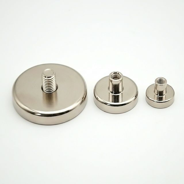
Connection-format example: these metal-finished bases do not show a rubber jacket.
5.1 Female Threaded Inserts
For a female threaded magnetic base, request a section drawing showing how the insert resists rotation and transfers axial and bending loads to the backing. Keyed, flanged, welded or swaged constructions need assembly-specific verification; appearance alone does not prove strength.
Specify maximum installation torque, minimum thread engagement, spin-out/pull-out acceptance and the proof-test procedure. There is no universal safe M4, M6 or M8 torque for an insert in a magnetic base. Avoid an impact-driver process unless the supplier has qualified it for that assembly.
5.2 Male Threaded Studs
For a male threaded pot magnet, verify stud material, attachment method, bracket seating and bending resistance. A fastener strength class does not rate a weld, rivet or thin backing plate. Agree on fatigue and proof testing for the assembled connection under the application's offset load.
6. Sourcing & Quality Audit Checklist
Use this checklist to make the quote and sample inspection reproducible. Set acceptance values with the responsible engineer before ordering samples.
- Load case: record payload in kg, forces in N, orientation, bracket offset, acceleration and consequences of detachment; assess independent retention where required.
- Contact surface: state steel grade, thickness, curvature, finish/paint thickness, flatness and expected contamination.
- Normal pull: obtain the named method, load-cell calibration, centered pull direction, plate saturation check, test temperature and individual readings. Identify both catalogue and actual-panel conditions.
- Sliding and creep: test the finished base on the actual vertical panel; record loading rate, dwell, first motion, allowable sustained displacement, sample count and acceptance rule. A force gauge needs a restrained test fixture, not an uncontrolled suspended payload.
- Peel and vibration: test the complete bracket at its real offset, fastener torque and service loads; do not substitute the simple friction calculation.
- Materials: record jacket compound, hardness method/tolerance, magnet grade, gap dimensions and insert construction. Hardness alone cannot identify a compound or establish its grip.
- Threaded connection: document installation torque, thread engagement and assembly-specific spin-out, pull-out and bending criteria.
- Aging and repeatability: define temperature, UV, moisture, salt or chemical exposure relevant to service, then repeat holding tests. Choose durations and pass limits for the application; chamber hours alone do not establish field life.
- Approval record: retain sample identities, raw readings, photographs, failures, accepted margins and the signed drawing revision. Record who approved the final working load.
A practical comparison uses the same base on a reference plate and the actual panel, then compares dry, contaminated and aged conditions using the agreed sample plan. Keep normal pull, onset of slip, sustained creep and peel results separate so an excellent result in one mode cannot hide a failure in another.
7. Frequently Asked Questions (FAQ)
Why does a 50 kg rated rubber coated magnet slide down a wall under an 8 kg load?
A 50 kg catalogue rating usually denotes kilogram-force in a normal pull test, not a permitted payload. On a vertical wall, sliding resistance depends on actual clamping force and surface friction. Paint, thin steel, contamination and an offset bracket can reduce the available margin. Measure pull, slip and peel performance on the installed surface.
How does rubber coating increase shear holding force if it reduces magnetic pull force?
Rubber may increase friction while adding a non-magnetic gap that reduces normal attraction. Whether usable shear improves depends on both effects together. Compare finished assemblies on the same substrate; do not assign a universal friction coefficient or improvement percentage from the coating name.
What safety factor should engineers specify for vertical or overhead magnetic mounts?
There is no universal safety factor for every magnetic mount. The responsible engineer must set acceptance margins for measured sliding, peel, fastener strength and dynamic loads. A static friction calculation cannot approve overhead, road-going or personnel-critical use; assess applicable requirements and independent mechanical retention.
How does steel sheet thickness affect the holding force of rubber pot magnets?
Steel grade, thickness, pole spacing, flatness and the complete non-magnetic gap affect the magnetic circuit. A rating measured on thick steel cannot be transferred directly to a thin painted panel. Request pull-force-versus-thickness data for the exact assembly and confirm performance on the intended panel.
Can standard rubber coated pot magnets withstand outdoor UV and automotive temperatures?
The rubber compound name alone does not establish an assembly temperature or outdoor rating. Check the exact compound, magnet grade, bonding system, seals and fastener design, then request aged pull and slip results at the required temperatures. An elastomer temperature limit is not an assembled magnet operating limit.
What prevents the threaded stud or insert from stripping out of the magnetic base?
The insert or stud needs a defined load path into the steel backing and verified resistance to spin-out, pull-out and bending. Specify installation torque, thread engagement and proof-test acceptance on the drawing. Thread diameter alone does not establish a safe torque or assembled-base strength.
8. Sources and Industry References
Reviewed on 2026-10-26. These sources define test methods and their limits; they do not supply measured performance for the pictured products or the hypothetical calculation above. Agree on the applicable edition and fixture with the testing laboratory.
- MDFA-101-95, reproduced by Integrated Magnetics: Test method for determining breakaway force of a magnet. Addresses normal detachment, test setup and optional gap-versus-force measurements. It does not rate a vertical bracket's shear or peel capacity.
- ASTM International, D1894: Static and kinetic friction of plastic film and sheeting. Use its stated scope when reviewing a friction report; an adapted molded-base fixture must disclose deviations and cannot establish an assembly working load on its own.
- ASTM International, D2240: Rubber property—durometer hardness. Supports a defined hardness inspection; it does not establish friction, compound identity or environmental life.
Request a Mounting and Sourcing Review
Contact CoatedMagnets with your panel material and thickness, finish, payload, load direction, bracket drawing/offset, operating environment and expected order quantity. Include any existing pull, slip or peel results. Request a proposed sample and acceptance-test plan before treating a catalogue rating as a working load; confirm any custom material or testing capability for your project during the review.