
Threaded Pot Magnets: Fastener Pull-Out Torque, Internal Core Adhesive Shear, and ISO 898-1 Thread Stripping Limits
Specify threaded pot magnets with checks for bolt pull-out, blind-hole depth and adhesive shear. Use examples and an RFQ checklist to request torque limits.
2026/11/03
Threaded pot magnets need assembly-specific tightening limits. ISO 898-1 describes fastener mechanical properties; it does not supply a universal safe installation torque or thread-stripping limit for a magnetic base. Magnetic pull-off force, axial fastener pull-out force and installation torque are three different quantities. A catalogue pull rating cannot establish either of the other two.
Content issue and technical review: 2026-11-03. Publisher: CoatedMagnets. This English-language guide serves global procurement teams, mechanical designers and fixture builders selecting threaded magnets and mounting styles. The issue date is an editorial record; public deployment has not been independently confirmed.
Scope and evidence: The guide concerns small threaded magnetic mounting assemblies, particularly female blind-threaded designs. Male studs, through-hole cups and integral bosses have different load paths. The numerical examples below are hypothetical calculations, not measured product performance, certified torque ratings or a completed VDI 2230 assessment. No supplier batch test report is supplied here. Use the examples to identify missing drawing and qualification inputs before releasing an assembly instruction. They do not establish suitability for overhead lifting or safety-critical retention.
Need to specify a mounting joint? Send the bracket drawing, thread specification and service-load envelope for review. Include the exact magnet part number; a thread diameter alone is insufficient.
The torque trap: a bolt rating is not a magnet assembly rating
A torque chart prepared for a structural steel joint assumes particular friction, engagement and bearing conditions. Transferring that setting to a shallow tapped cup can overload the weaker mating thread or retention feature. The result depends on construction: failure is possible, rather than inevitable at one nominal torque.
For scale, the approximate relation F = T / (K × d) gives 8,333 N at 10 N·m for an M6 screw when the assumed nut factor K is 0.20. At 24 N·m, the same assumption gives 15,000 N for M8. These are calculation inputs, not ISO torque prescriptions. Changing plating, lubrication, threadlocker or bearing geometry changes K and therefore the preload at the same wrench setting. The NASA Fastener Design Manual, printed page 16 discusses this approximation and warns against using an assumed coefficient without checking the joint.
Ask how the mounting assembly is built before selecting a limit:
- Steel cup with integral threaded boss: Thread and cup strength, local bearing and deformation can govern. Installation reaction need not pass through the magnet adhesive.
- Separately retained threaded insert: Bonding, press fit, staking or a mechanical key may resist insert rotation and axial pull-out. Each retention method needs its own evidence.
- Sintered magnet core: The core is brittle. A bolt tip or distorted housing can introduce damaging local contact and bending; a bulk compressive-strength number cannot predict the assembled part's fracture load.
- Rubber or polymer covering: A coating can improve surface protection and friction, while also introducing compliance and an air gap. Its temperature range is separate from the adhesive and magnet-grade limits.
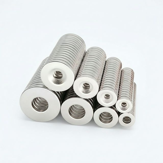
1. Thread engagement and fastener pull-out
Thread stripping is an axial-load failure. Installation torque contributes by creating preload, but there is no one-to-one torque-to-pull-out conversion without friction and geometry information. In service, external tension, bending and load distribution can further change the force carried by the fastener.
A transparent screening model
For an initial sensitivity calculation, define an approximate internal-thread shear area:
A_shear = pi × d × L_e × q
F_allow_screen = A_shear × tau_allow
Here d is nominal diameter, L_e is effective full-thread overlap, q is an assumed dimensionless geometry factor, and tau_allow is an already-derated allowable shear stress for the actual internal-thread material. Use mm and N/mm² consistently to obtain N. This simplified area model does not represent the detailed thread geometry, radial expansion, uneven load sharing or thin-wall effects covered by a complete joint analysis. It is not a quoted VDI equation.
The public VDI 2230 Part 1 description identifies a systematic calculation framework for highly stressed bolted joints. Do not turn that reference into a blanket statement that every pot magnet needs 1.2d or 1.5d engagement. A required overlap must follow from the design loads, mating materials, thread tolerances and failure model. A deeper hole alone also cannot establish adhesive or cup capacity.
Blind depth is not effective engagement
A depth probe can reach a drilled cavity floor beyond the last complete female thread. The entrance chamfer, tap runout and screw-tip lead reduce usable overlap. Record minimum physical depth, minimum full-thread depth and screw penetration as separate dimensions. For example, a hypothetical 4.5 mm-deep cavity with 0.5 mm of entrance chamfer and 1.0 mm of bottom runout cannot offer 4.5 mm of complete internal thread.
A thread plug gauge checks size and fit; it does not by itself certify blind-hole depth or prove pull-out capacity. Specify a depth measurement method and an engagement inspection separately. If the drawing lacks these dimensions, the sourcing decision is to request them rather than infer them from the overall magnet height.
2. Failure paths inside the mounting assembly
The schematic below shows possible load paths in a bonded-insert design. It is not to scale and does not describe every catalogue product. In an integral-boss design, metal may bypass the illustrated adhesive reaction path. The target plate is drawn separated from the magnet for clarity; actual holding performance depends on contact, coating thickness, target material and air gap.
Mechanical Load Paths, Thread Shear Vectors, and Internal Adhesive Boundaries in Threaded Pot Magnets
3. Prevent bolt bottoming before setting torque
A screw can feel tight while leaving the bracket unclamped if its tip reaches the hole floor first. That false seating condition can damage the cup, insert or core. The exact outcome depends on the section design; neither inevitable shattering nor a fixed percentage loss of magnetic force can be predicted from screw length alone.
For a conventional bolt whose nominal length is measured beneath its head, define:
penetration = bolt length - bracket thickness - washer stack
clearance = minimum physical hole depth - maximum penetration
Use the actual seating datum for countersunk screws. The worst-case penetration uses the longest permitted screw and thinnest permitted bracket and washer stack. The clearance must remain positive by a drawing-specific allowance; one nominal thread pitch or a fixed 1.5-pitch rule is not a substitute for tolerances and the supplier's tip-clearance requirement.
Inspect both requirements independently: enough complete thread overlap to carry the calculated load, and enough tip clearance to prevent bottoming. Shortening a screw may solve interference while leaving insufficient engagement. Conversely, increasing engagement by choosing a longer screw may recreate the bottoming problem. If both cannot be met, change the bracket stack, mounting style or magnet boss geometry.
4. Adhesive shear and insert spin-out
A bonded insert can rotate if the reaction torque exceeds its retention capacity. The relevant torque is the torque actually transmitted across that interface, called T_bond here. It is not automatically the entire wrench torque: thread reaction, under-head friction, fixture restraint and any metal interlock determine the load path.
For an ideal cylindrical bonded interface of radius r and bonded height h, assuming uniform shear:
tau_average = T_bond / (2 × pi × r² × h)This is a torsional-equilibrium estimate for a cylindrical surface. It does not apply unchanged to an annular end-face bond, a partly filled gap or a crimped joint. It also omits edge peaks, peel stress, voids and creep. Identify the real interface on a section drawing before using the equation.
Worked bondline sensitivity example
Assume a fully bonded cylindrical insert with r = 6 mm and h = 7 mm. Set T_bond = 15 N·m, or 15,000 N·mm, solely as an illustrative load case. The denominator is 2 × pi × 6² × 7 = 1,583 mm³, so average shear is 9.47 MPa. At an assumed T_bond of 24 N·m it becomes 15.16 MPa. These results describe calculated demand, not a measured failure boundary.
There is no supplied adhesive allowable against which to approve either result. ASTM D1002 concerns apparent shear strength of metal single-lap adhesive specimens; a test-method reference is not a universal epoxy strength value or a torsional rating for a plated pot magnet. Request the adhesive identity, surface preparation, cure schedule, bond geometry and retention test at the intended service temperature. Avoid substituting an unsupported percentage reduction for real hot and aged data.
Knurling, keyed inserts and mechanical staking can change how torque is carried. They do not justify assigning generic MPa capacities to each construction. Qualification should include installation and removal, because cured threadlocker can increase the torque needed to dismantle the joint and expose an insert to a different load case.
Ask about the thread and insert construction available for your bracket before specifying a torque driver setting. Include whether the assembly must be removable after cure and environmental exposure.
5. Thread-size procurement table: inputs, not safe torque ratings
The table covers common metric and UNC coarse threads. It provides nominal identification and axial travel to help spot ordering and length-stack errors. It intentionally gives no universal safe torque, blind depth or minimum engagement. Those values require the selected part's drawing and test evidence. UNC sizes do not acquire metric ISO property classes by analogy.
| Thread designation | Nominal diameter | Pitch / axial travel per full turn | Travel per quarter-turn | Required supplier confirmation |
|---|---|---|---|---|
| M4 × 0.70 | 4.00 mm | 0.70 mm | 0.175 mm | Full-thread depth, cup material and assembly torque limit |
| M5 × 0.80 | 5.00 mm | 0.80 mm | 0.200 mm | Effective overlap and insert retention method |
| M6 × 1.00 | 6.00 mm | 1.00 mm | 0.250 mm | Screw length stack and qualified tightening conditions |
| M8 × 1.25 | 8.00 mm | 1.25 mm | 0.313 mm | Anti-rotation capacity and adhesive temperature evidence |
| M10 × 1.50 | 10.00 mm | 1.50 mm | 0.375 mm | Boss wall thickness, bearing support and cup distortion limit |
| 1/4-20 UNC | 6.35 mm | 1.270 mm | 0.318 mm | UNC thread fit, depth and specified fastener grade |
| 3/8-16 UNC | 9.525 mm | 1.588 mm | 0.397 mm | UNC engagement and installation/removal qualification |
Pitch values describe nominal coarse-thread geometry; rounded travel values are not inspection tolerances. Check the drawing designation, including pitch and thread fit. An M6 screw and a 1/4-20 screw are not interchangeable even though their nominal diameters are close. Never force a partial fit to identify a thread.
6. Hypothetical fixture example: separate fit from qualification
This worked example is a dimensional and load-screening exercise, not a customer case or observed test. Consider a sensor bracket with four magnetic mounts, an 8.0 mm-thick bracket and an M6 female-threaded mount. Assume a 180 N external shear load. Lever arm, vibration spectrum and service friction remain unknown, so the example cannot establish a released design.
Step 1: Reject the original length stack
The original proposal uses an M6 × 16 screw without a washer and a physical blind depth of 6.5 mm. Penetration is 16 - 8 = 8 mm. The tip reaches the floor 1.5 mm before the intended stack seats. Reject that proposal before any torque trial. Tightening a bottomed screw cannot supply a reliable bracket clamp.
For comparison, an M6 × 12 screw with a 1.5 mm washer gives 12 - 8 - 1.5 = 2.5 mm penetration. It avoids nominal bottom contact but still needs a separate engagement calculation; a positive clearance alone is not approval.
Step 2: Define a deeper-boss proposal consistently
Suppose a revised drawing offers minimum physical depth 10.0 mm and complete female threads extending from 0.5 mm to 8.5 mm below the entrance. Retain the M6 × 16 screw with the 8.0 mm bracket and 1.5 mm washer. Nominal penetration becomes 6.5 mm, leaving 3.5 mm physical tip clearance.
If the screw-tip lead occupies the final 0.5 mm, the complete external thread extends only to 6.0 mm. The overlap with the specified complete female thread is therefore 6.0 - 0.5 = 5.5 mm. These are nominal illustrative dimensions; a release drawing must repeat the calculation at tolerance extremes. Confirm that the supplier can actually provide the proposed boss rather than treating it as an available catalogue feature.
Step 3: Show the sensitivity of a proposed torque
Take 4.0 N·m as a hypothetical trial input, not a recommended M6 torque. With d = 0.006 m and K = 0.20, estimated preload is 4 / (0.20 × 0.006) = 3,333 N. If the assumed K instead ranges from 0.15 to 0.25, estimated preload ranges from 2,667 to 4,444 N.
Using the simplified screen with q = 0.60 and L_e = 5.5 mm gives A_shear = pi × 6 × 5.5 × 0.60 = 62.2 mm². The corresponding average demand ranges from 42.9 to 71.5 MPa. An assumed allowable of 80 MPa would give a demand ratio margin of only 80 / 71.5 = 1.12 at the high-preload end. That assumed allowable has not been established for this component, and the screen omits local effects. None of these numbers qualifies the joint as safe.
Step 4: Check the magnetic service load separately
For another explicitly assumed scenario, four mounts with 300 N normal attraction each and a surface friction coefficient of 0.15 would provide 4 × 300 × 0.15 = 180 N of idealized sliding resistance. That merely equals the assumed 180 N shear load, leaving no allowance for variation, contamination, vibration or overturning. These inputs are not a product rating.
Bolt preload attaches the bracket to each mount; it does not add the same force to magnet-to-target attraction. Cantilever offset and mount spacing must be known to assess peel and load sharing. The purchasing outcome is to request actual application pull/slip data and geometry, rather than release the design from a bolt torque calculation.
7. Fastener selection and receiving checklist
Use this checklist to turn missing information into a concrete drawing or RFQ request. Acceptance values belong to the selected assembly and application; the checklist does not create new ratings.
| Check | What to specify or request | Verification / acceptance basis |
|---|---|---|
| 1. Thread identity | Diameter, pitch, fit and exact mount part number | Drawing plus appropriate thread gauge |
| 2. Hole geometry | Physical depth, complete-thread depth, chamfer and runout | Supplier section and separate depth inspection |
| 3. Screw stack | Head datum, bracket, washer, tip lead and tolerances | Worst-case overlap and clearance calculation |
| 4. Installation limit | Torque range, restraint method, speed and friction condition | Supplier-approved instruction and assembly trial |
| 5. Insert retention | Integral boss, adhesive, press fit, key or staking | Axial and torsional evidence for that construction |
| 6. Adhesive environment | Resin, cure, surface preparation, temperature and exposure | Relevant assembly retention testing after conditioning |
| 7. Fastener specification | Property class or grade, coating and corrosion compatibility | Material documentation; lower strength is not automatic protection |
| 8. Bearing and locking | Metal seating surface, washer and any threadlocker process | Fit inspection, friction assessment and loosening evaluation |
| 9. Service holding | Target material/thickness, coating, gap, shear and moment | Pull, slip and peel tests in the intended setup |
| 10. Post-installation condition | Cracks, insert rotation, distortion and holding change | Agreed inspection and comparison with an untorqued baseline |
A surface gaussmeter reading may help detect a change under a controlled setup, but it is not the intrinsic remanence Br and does not replace a holding-force test. Similarly, a lap-shear coupon certificate cannot alone qualify the complete insert. Agree on sample sizes, acceptance criteria and whether a proof test is destructive before testing saleable units; do not invent a universal 1.5-times-torque proof rule.
For threadlocker, follow the selected manufacturer's instructions for cleaning, dosage, cure and any activator. Reassess torque-to-preload behavior while uncured and removal torque after cure. Changing from dry threads to adhesive-treated threads is a process change, not merely a purchasing substitution.
Frequently asked questions
Does ISO 898-1 specify safe tightening torque for threaded pot magnets?
No. ISO 898-1 concerns mechanical properties of carbon-steel and alloy-steel fasteners. It does not give a universal installation torque or thread-stripping limit for a pot magnet. Obtain the assembly-specific torque limit, mating-thread material, engagement and test conditions from the magnet supplier.
What is the minimum thread engagement length for a female threaded pot magnet?
There is no single minimum that applies to every pot magnet. Required engagement depends on the internal-thread material, thread geometry, wall thickness, preload and service loads. Exclude incomplete threads and chamfers, then verify the actual design by calculation and supplier assembly testing.
What happens if a bolt bottoms out in a blind-threaded pot magnet?
The bolt can contact the cavity floor before the bracket is clamped. Further tightening may deform the cup, damage an insert or crack the magnet, depending on construction. Check penetration against minimum available hole depth, including washers, tolerances and an explicit tip clearance.
How can tightening torque damage the internal adhesive bondline?
A separately bonded insert may transmit reaction torque through its adhesive joint. An integral steel boss can carry that reaction through metal instead. For a cylindrical bonded interface, average shear is T_bond divided by 2 pi r squared h; actual strength requires evidence for the specific adhesive, geometry, cure and environment.
Can threadlocker replace mechanical tightening torque?
Threadlocker may supplement resistance to loosening, but it does not replace required clamp force or repair insufficient engagement. It can change assembly friction and cured removal torque. Qualify the exact product, dosage, surface preparation and cure with the selected magnet assembly.
Which washer should be used with a threaded pot magnet?
Use a washer arrangement that supports the bracket on a defined metal bearing surface and fits the available screw-length stack. A flat washer can distribute load; split or conical spring washers should be used only when their bearing loads and travel have been assessed. No washer increases the internal thread or adhesive rating.
Technical sourcing and the next decision
Select the threaded magnet mounting style first, then close the drawing and qualification gaps. A female blind thread, male stud and through-hole fastener should not share an installation instruction solely because their nominal thread sizes match.
Send your assembly brief to CoatedMagnets with the bracket stack, screw type, thread pitch, target surface, expected forces and moments, temperature, exposure and removal requirements. Mark unknown values explicitly. Request the proposed section drawing, part-specific torque limits and supporting retention evidence before approving production assembly. This guide offers a review framework; it does not promise a tested custom construction or a torque rating for an unspecified product.
Sources and engineering references
Reference access review: 2026-11-03. VDI's public description and the NASA manual were accessible during this review. ISO and ASTM catalogue pages restricted automated access; their full standards were not reviewed here. Catalogue references identify standards and scope, not certification of the worked examples. Confirm the contractually required edition when preparing a specification.
- ISO 898-1:2013 — Mechanical properties of fasteners made of carbon steel and alloy steel. Reference for applicable metric bolt, screw and stud mechanical properties. It is not a pot-magnet installation torque table or an assembly-specific stripping limit.
- VDI 2230 Part 1 — Systematic calculation of highly stressed bolted joints. Joint-calculation framework. The public overview does not substantiate a universal engagement ratio or the simplified screen used here.
- ASTM D1002-10(2020) — Apparent shear strength of single-lap-joint adhesively bonded metal specimens. Adhesive test-method reference, not a source of generic epoxy torsional allowables or a specified temperature reduction.
- NASA Reference Publication 1228 — Fastener Design Manual, Richard T. Barrett, 1990. See printed page 16 for torque/preload approximations and printed page 21 for tapped-hole pull-out analysis. It provides general engineering background, not a qualified magnet mounting rating.