
Magnetic Cable Mounts in Solar & Industrial Wire Routing: DIN EN IEC 62275 Retention Limits, Wind Shear Flutter & Galvanic Isolation Engineering
Specify magnetic cable mounts for solar and industrial routing. Review DIN EN IEC 62275 scope, wind loads and corrosion limits; prepare your engineering RFQ.
2026/11/10
Specify magnetic cable mounts from the complete assembly's performance on your steel and coating stack, rather than its catalog pull rating alone. For solar photovoltaic (PV) trackers and industrial wire routing, the purchasing decision covers three interfaces: cable to tie, tie to saddle, and magnetic base to structure. A strong tie cannot compensate for a base that slides or peels away.
Published and editorially reviewed: 2026-11-10. Publisher: CoatedMagnets. This engineering guide serves solar EPCs, electrical balance-of-plant contractors, control panel designers and procurement teams comparing magnetic cable mounts and cable holders.
Scope and evidence limits: This is a global sourcing framework for ferromagnetic steel supports. Local electrical rules, structural approvals and equipment installation instructions govern the actual project. The numerical example uses hypothetical inputs, not product test results or a customer installation. No certification or service-life claim is made for the illustrated assembly. Magnetic retention does not establish protective earthing, electrical insulation or strain-relief compliance.
Preparing a wire-management RFQ? Send your routing drawing and substrate specification with bundle weight, mounting orientation and environmental conditions to discuss the qualification evidence before ordering samples.
The Structural Sourcing Conflict: Drilling, Welding and Magnetic Fastening
Cable supports must retain conductors without abrasion, excessive sag or damaging movement. Solar trackers add articulation and repeated thermal movement; industrial cabinets may add oil, washdown or machinery vibration. Establish these conditions before selecting an attachment method.
Drilled fasteners provide a positive mechanical connection, but the hole can expose steel beneath a protective coating. Whether drilling is permitted, and what repair method is required, depends on the structural design and OEM warranty. Obtain written approval rather than assuming every drilled hole automatically voids every warranty.
Welded studs also need structural approval and a coating-repair procedure. Welding can damage adjacent zinc or paint and may require hot-work controls. Compare the finished, repaired connection and installation access with the alternatives; a generic salt-spray number cannot predict the life of the repaired structure.
Magnetic mounting avoids penetration and allows repositioning. Its trade-off is dependence on surface contact, magnetic circuit geometry and loading direction. It requires a ferromagnetic target: aluminum, many stainless grades and non-metallic trays cannot be accepted merely because they look like steel. A curved torque tube may provide less contact area than a flat laboratory plate.
Include installation labor, inspection access, replacement procedures and the consequences of a dropped cable in the sourcing comparison. If retention evidence is missing, use an approved mechanical support or secondary restraint while qualification remains open.
1. The Standards Gap: DIN EN IEC 62275 and Magnetic Retention
IEC 62275:2022 addresses cable ties and associated fixing devices used to manage or secure wiring. Its published scope notes that supporting wiring can introduce additional requirements. A DIN EN IEC 62275 reference in an RFQ should identify the national adoption and edition rather than assuming every regional edition shares the IEC publication year.
What to Ask for in the Compliance Report
Request the exact model, tie width, saddle configuration, mechanical rating, attachment method and conditioning covered by the report. Check whether the fixing device was tested as a complete magnetic assembly or attached to a rigid fixture by another method. A certificate for a plastic saddle cannot automatically extend to a new magnet, screw or overmold combination.
Do not infer Type 1 or Type 2 classification from whether a saddle is integral or whether its boot is EPDM or TPV. Ask the supplier to identify the classification and acceptance criteria from its applicable report. A polymer flammability rating is not a magnetic retention rating, and a corrosion exposure method is not a cable-support certification.
Split the purchase specification into two evidence requests:
- Cable-and-saddle performance: approved tie combination, mechanical rating, temperature limits and relevant outdoor conditioning, with report scope stated explicitly.
- Structural attachment performance: normal pull-off, lateral sliding and loading at the actual bundle standoff, using the project's steel thickness, curvature, coating and surface condition.
An acceptable submittal identifies covered configurations and remaining unqualified conditions. For North American projects, confirm the required listing and installation conditions with the project authority; an IEC document number alone does not establish local acceptance.
2. Dynamic Failure Modes: Wind Shear, Cantilever Peel and Thin Steel
2.1 Separate Mean Wind Drag from Dynamic Response
A first screening calculation for a bundle exposed across the wind is:
q = 0.5 × rho × v²                     [N/m²]
w_wind = q × C_d × D_bundle            [N/m]
Here, rho is air density, v is the selected wind speed, C_d is the assumed drag coefficient and D_bundle is projected bundle diameter. These equations estimate mean drag under stated assumptions. Project wind design also needs the governing exposure, height, direction, gust treatment and load combinations. Check how the selected wind-speed definition is used before adding or removing factors.
Wind-induced vibration and flutter are separate questions. For a simplified cylindrical body, f_s = St × v / D_bundle estimates a shedding frequency. With assumed St = 0.20, v = 33.3 m/s and D_bundle = 0.026 m, the result is approximately 256 Hz. That arithmetic does not establish resonance with a cable span or predict tracker flutter. Geometry, shielding, tension, damping and structural modes need their own assessment.
Ask for cyclic-loading or vibration evidence relevant to the installation, especially near moving joints and exposed array edges. A mean-drag calculation cannot establish fatigue resistance or freedom from progressive displacement.
2.2 Sliding and Overturning Are Different Limits
For a friction-only screening model:
F_slide ≈ mu × F_normal
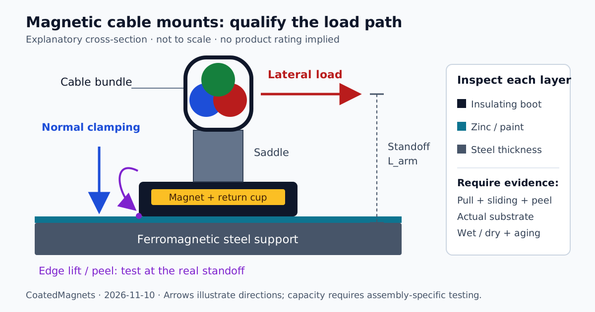
L_arm = h_saddle + D_bundle / 2
M_overturn = F_lateral × L_arm
The coefficient mu belongs to a particular surface pair and condition. Rubber can increase friction while adding a non-magnetic gap; moisture, dust, oils and wear change contact and sliding behavior. Request wet and dry assembly tests rather than a universal coefficient assigned by material name.
Bundle standoff converts lateral force into a moment. Edge lifting changes the contact and magnetic circuit, so pull-off capacity cannot be converted into peel capacity by a generic lever-ratio multiplier. Test the complete assembly at the intended saddle height, load direction and orientation. Define a limit for first slip, displacement or detachment; these are different acceptance criteria.
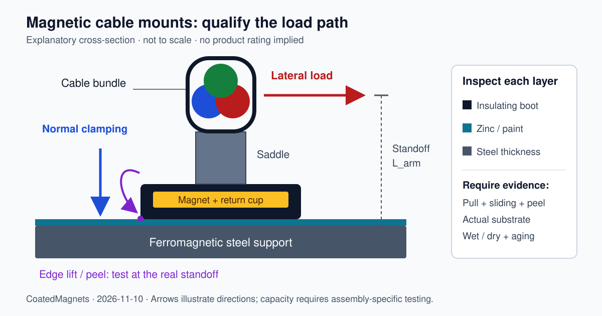
CoatedMagnets explanatory schematic, 2026-11-10; not to scale. Arrows distinguish lateral loading from normal clamping. The insulating layer is a design feature to inspect, not evidence of a tested product or certified electrical barrier. Open the scalable diagram for label detail.
2.3 Steel Thickness and the Total Non-Magnetic Gap
Steel completes the magnetic circuit. Thin or curved supports can produce different holding forces from thick, flat laboratory plates. The amount depends on pole geometry and steel properties; there is no universal minimum steel thickness or percentage loss for every base.
Record all layers between the effective pole face and the ferromagnetic steel: boot, zinc, paint, dirt and separate protective pads. Metallic zinc does not provide a useful ferromagnetic return path. Uneven surfaces may create larger local separations than nominal coating thickness suggests.
There is no general exponential loss percentage for a one-millimeter gap. Request force-versus-gap data for the exact assembly and representative steel gauges. Establish the catalog rating's reference plane: a rating measured on the finished rubber-coated mount already includes the boot, so applying another boot penalty would double-count it.
3. Galvanic Isolation and Environmental Corrosion
ISO 12944-2:2017 provides environmental corrosivity classifications for protective-paint selection. It helps describe exposure but does not certify a mount's isolation or service life. Specify actual salt deposition, condensation, immersion or washdown conditions rather than assigning every coastal location to one category.
Galvanic corrosion requires an electrical connection between conductive surfaces and an electrolyte. A nickel-plated cup contacting zinc-coated steel can create a different couple from two similar zinc-coated surfaces. Exposed areas, coating defects, drainage and electrolyte chemistry affect the result. Do not treat every plated cup as equally incompatible or assign fixed electrode potentials to every commercial assembly.
An intact insulating overmold can interrupt direct contact and protect the core. Protruding screws, damaged edges, conductive debris or contaminated water can bypass or undermine that protection. Inspect the complete fastener path and the condition beneath the base after representative cycling.
Specify compound identity, adhesion, operating temperatures and site-chemical compatibility. EPDM, TPV and polyurethane have formulation-dependent properties rather than interchangeable lifetime ratings. Include abrasion: an overmold surviving static salt fog may still wear through during repeated movement.
ASTM B117-19 describes a controlled salt-fog exposure method. Its published limitations explain why salt-spray results alone do not reliably predict natural-environment performance. Agree exposure duration and acceptance criteria, then remeasure functional retention afterward. A 1,000-hour result cannot independently establish 20 or 25 years of field life. B117-19 is a historical edition; agree the applicable edition for new work.
4. Engineering Comparison Matrix: Cable Mount Architectures
Use this seven-row matrix to select evidence requests. It compares design considerations, not measured product rankings. Certification, pull force, friction, temperature limits and life expectancy belong to the specific supplied model.
| Mounting architecture | Potential sourcing benefit | Main installation limit | Evidence before approval |
|---|---|---|---|
| TPV-overmolded base with tie saddle | Repositionable support with protective contact layer | Boot thickness, wear and contamination affect retention | Wet/dry sliding and standoff-load tests; compound and UV records |
| EPDM-encapsulated pot magnet | Candidate for suitable outdoor environments | Fluid compatibility and seal durability are application-specific | Chemical compatibility, aging and post-aging pull/peel results |
| Nickel-plated pot magnet with separate saddle | Compact assembly for controlled environments | Exposed conductive contact and low-friction surfaces | Plating specification, sliding tests and corrosion assessment |
| Polyurethane-coated magnetic bridge | Wider footprint and larger-bundle routing options | Curvature, hydrolysis resistance and load sharing | Compound data and complete-bridge testing on the actual profile |
| Stainless-enclosed magnetic assembly | Candidate where enclosure cleanability matters | Shell thickness adds separation; stainless can couple with zinc | Enclosure integrity, isolation detail and assembled retention |
| Zinc-plated stamped magnetic clip | Simple component with limited assembly complexity | Edge protection, coating wear and retention scope | Model-specific compliance and conditioned retention records |
| Mechanical edge clip, non-magnetic baseline | Positive engagement at an approved accessible edge | Edge geometry, coating damage and cable clearance | OEM-approved installation, extraction force and coating assessment |
Shortlisting an architecture? Request a sample-review discussion using the same coupon, coating stack and load direction as the acceptance test. Comparing those conditions is more useful than catalog kilogram ratings.
5. Worked Sizing Example: Solar Tracker Cable Run
All capacity values below are hypothetical teaching inputs, not CoatedMagnets product specifications. The result illustrates screening; it does not approve an installation or replace governing wind and electrical design.
Design Case Inputs
- Mounting plane: vertical steel face; wind and weight act in perpendicular directions within that plane. Other orientations require different load components.
- Substrate: assumed 2.0 mm flat steel, 0.08 mm zinc and 0.10 mm paint.
- Assembly: assumed 0.80 mm boot and 12 mm saddle height.
- Bundle: assumed 26 mm projected diameter and 0.55 kg/m total supported mass.
- Wind: assumed
v = 33.3 m/s,rho = 1.225 kg/m³andC_d = 1.2. - Load sharing: equal interior spans under uniform loading; one span length tributary to each interior mount. Terminal tension and tracker-joint forces are excluded.
Step 1: Define the Test Stack and Standoff
t_gap = 0.80 + 0.08 + 0.10 = 0.98 mm
L_arm = 12 + 26 / 2 = 25 mm = 0.025 m
The gap is referenced from the assumed uncoated pole face. It identifies a test condition, not a holding force. Suppose, for arithmetic only, normal clamping on this stack is 94.6 N and mu = 0.50. The friction-only estimate is 47.3 N. Neither input is verified here, and that estimate omits peel and displacement limits.
Step 2: Calculate Wind and Weight per Meter
q = 0.5 × 1.225 × 33.3² = 679.2 N/m²
w_wind = 679.2 × 1.2 × 0.026 = 21.2 N/m
w_weight = 0.55 × 9.81 = 5.40 N/m
w_resultant = sqrt(21.2² + 5.40²) ≈ 21.9 N/m
Wind and weight both act in shear on this vertical mounting face. With an underside-mounted support, weight adds normal separation load and this calculation would be incomplete. Use actual vector directions and tributary lengths at corners, terminals and unequal spans.
Step 3: Use Assembly Capacity at the Real Standoff
Assume a future qualification program establishes a lower-bound onset limit of 33.2 N for the complete assembly at 25 mm standoff, across relevant in-plane load directions and conditioned surfaces. This assumption incorporates sliding and peel in the proposed test setup; it is not derived from normal pull.
For arithmetic only, choose SF = 1.5:
F_screen = 33.2 / 1.5 = 22.1 N per mountThis is not a prescribed standards factor or a substitute for gust, fatigue, aging or load-combination requirements. The responsible engineer determines the design basis and how tested lower-bound capacity becomes an allowable load.
Step 4: Screen Spacing and Record Open Decisions
L_screen = 22.1 / 21.9 ≈ 1.01 m
At 1.0 m: resultant load ≈ 21.9 N; moment ≈ 0.55 N·m
At 1.5 m: resultant load ≈ 32.9 N
Under these rounded assumptions, a one-meter candidate is close to the screening limit; 1.5 meters exceeds it. Neither is approved because actual capacity and project factors remain unresolved. Cable sag, jacket pressure, bend radius, moving-joint travel and thermal slack can impose tighter limits even when a force check passes.
The procurement deliverable is a conditional test request: qualify the assembly on the stated stack at the actual standoff and provide evidence for the allowable-load decision. Do not issue this example as a universal spacing instruction.
6. Sourcing and Receiving Checklist for Procurement Engineers
Use these ten checkpoints for a reviewable supplier submittal. Acceptance values come from the approved project specification; there are no universal thresholds implied by the table.
| Checkpoint | Parameter to verify | Record or acceptance decision |
|---|---|---|
| 1. Assembly identity | Base, saddle, fastener and tie combination | Drawing revision, part numbers and report scope match production |
| 2. Cable compatibility | Tie width, bundle diameter and jacket contact | Approved tension, bend radius, clearance and edge protection |
| 3. Outdoor polymer evidence | Compound, color and environment | Traceable UV/temperature conditioning and retained mechanical performance |
| 4. Overmold integrity | Thickness, adhesion and exposed metal | Inspection method and defect limits after abrasion and aging |
| 5. Substrate retention | Steel grade, gauge, curvature and coating | Pull tests on representative coupons; fixture and loading rate recorded |
| 6. Sliding and peel | Direction, standoff and permitted movement | Wet/dry results distinguishing first slip from detachment |
| 7. Isolation path | Boot, screw and conductive bypasses | Corrosion-isolation inspection; separate electrical safety requirements |
| 8. Thermal and motion exposure | Magnet grade, tie properties and tracker travel | Full assembly limits and retained capacity after agreed cycling |
| 9. Corrosion exposure | Method, edition, duration and criteria | Record rust, blistering and seal damage; repeat retention afterward |
| 10. Lot acceptance | Traceability, sampling and disposition | Agreed sample size, acceptance criteria and lot-linked results |
Check that reports apply to the production configuration rather than an earlier prototype. Boot compound, magnet geometry, saddle screw and tie-supplier changes may affect qualification. Define which substitutions require renewed testing before accepting them.
Frequently Asked Questions
Does DIN EN IEC 62275 certify the magnetic holding force of a cable mount?
A standard designation alone does not establish field holding force. IEC 62275 covers cable ties and associated fixing devices, so inspect the exact assembly, attachment method, conditioning and loading covered by the report. Require project-substrate pull, sliding and peel evidence where those conditions are absent.
Why do magnetic cable mounts slip under high wind gusts on solar trackers?
Catalog pull force describes separation normal to a specified test surface. Wind drag can act parallel to that surface, where sliding depends on friction and actual clamping force. Bundle standoff also creates an overturning moment. Wet surfaces, thin steel, gaps and cyclic movement can change the failure load.
How does hot-dip galvanizing or paint affect magnetic cable mount retention?
Zinc, paint and the protective boot separate the magnet from the ferromagnetic steel. Holding force generally decreases as this non-magnetic gap increases, but the reduction depends on the complete magnetic circuit and steel thickness. Use assembly-specific data and avoid counting the boot twice if the catalog rating already includes it.
Can bare metal pot magnets cause galvanic corrosion on galvanized steel beams?
Dissimilar conductive surfaces can form a galvanic couple when electrically connected in an electrolyte. Risk depends on plating, exposed areas and environment. An intact insulating overmold can interrupt contact, but damaged material, exposed fasteners or conductive contamination can bypass it. Isolation is not a lifetime corrosion guarantee.
What spacing should be used for magnetic cable mounts on a solar tracker?
There is no universal spacing. Determine tributary wind and weight loads, installation orientation, saddle standoff, cable sag, tracker movement and qualified assembly capacity. The one-meter candidate in this guide is an illustrative calculation with hypothetical inputs; it is not an approved installation spacing.
What polymer should be specified for outdoor cable tie saddles?
Request an outdoor-rated compound and evidence for the complete saddle-and-tie assembly at the project temperatures, UV exposure and chemical conditions. Weather-stabilized PA66 and PA12 are candidates, but polymer name or black color alone does not establish suitability. Accelerated exposure hours do not independently prove a 20-year service life.
Technical Sourcing and Requesting an RFQ
Selecting magnetic cable mounts requires an agreed load envelope and traceable configuration. Start with the support profile, steel thickness, coatings, bundle schedule and orientation. Include site conditions, temperatures, tracker movement, target quantity and compliance documents.
Separate desired project life from demonstrated qualification. Ask which reports exist, which tests need project coupons and how sample approval connects to the production drawing. Keep unresolved evidence visible during quotation review rather than treating it as an assumed capability.
Send your cable-routing drawing and RFQ specification to CoatedMagnets to discuss coated assembly options, sample requirements and available documentation.
Sources and Engineering References
Source records checked for this editorial review on 2026-11-10. Public records establish scope and limitations; they do not replace full standards or assembly test reports.
- IEC 62275:2022 — Cable management systems — Cable ties for electrical installations. Publisher record for ties and associated fixing devices; additional requirements can apply to wiring support. Confirm the national adoption and edition for the project.
- ISO 12944-2:2017 — Classification of environments. Publisher record for environmental corrosivity categories used in protective-paint selection. It does not establish a mount's service life or isolation rating.
- ASTM B117-19 — Standard Practice for Operating Salt Spray (Fog) Apparatus. Historical edition explaining exposure conditions and field-life extrapolation limits. Select the contractually applicable edition and product acceptance criteria separately.