
Autoclave Sterilization & Medical-Grade Coated Magnets: ISO 10993 Biocompatibility, 134°C Steam Durability & Encapsulation Engineering
Specify medical coated magnets for 134°C steam: compare encapsulation, scope ISO 10993 evaluation, and use the RFQ checklist to request validation evidence.
2026/11/07
For medical coated magnets exposed to 134°C steam, select the core and the moisture barrier separately, then qualify the finished assembly. A coating name cannot establish biocompatibility, a temperature rating cannot establish autoclave life, and a leak-test result cannot establish clinical safety.
Published and reviewed: 2026-11-07. Publisher: CoatedMagnets. This guide supports design engineers, medical-device OEM buyers and quality teams worldwide who need to compare encapsulation routes and prepare an RFQ. It is a component selection framework for reusable instruments, external fixtures and diagnostic assemblies. Implantable devices require a separate evaluation of long-term contact, retention, failure consequences and applicable regulatory requirements.
Evidence boundary: No original autoclave test dataset, clinical validation or qualified product lifetime is presented here. The comparison table contains engineering screening questions, not measured rankings or certifications. The device manufacturer and its qualified laboratory must define acceptance criteria for the intended use and target market.
Already preparing a drawing package? Request an encapsulation feasibility review with the installed gap, required force and full reprocessing sequence.
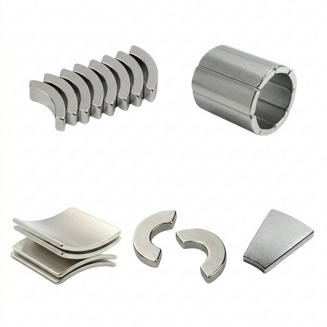
Figure 1: Product image illustrating magnet shapes. Appearance does not demonstrate coating chemistry, absence of pinholes, biological safety or autoclave durability.
1. Why Catalog Magnets Can Fail in the Autoclave
Medical magnets appear in positioning couplers, instrument fixtures and diagnostic mechanisms because they provide compact holding and alignment. Qualification becomes difficult when a prototype selected by room-temperature pull force must survive cleaning, sterilization, handling and storage throughout its claimed reuse life.
The CDC steam sterilization guidance explains that exposure depends on temperature, time, load and sterilizer type. Its examples include 121°C gravity-displacement and 132°C prevacuum processing, with 132–135°C cycles also discussed. These examples are not interchangeable device instructions. For a 134°C design target, obtain the actual validated cycle, including pre-vacuum, exposure, exhaust, drying and cooling. Distinguish absolute pressure from gauge pressure when specifying the process.
Failure Mode 1: Irreversible Thermal Demagnetization
Heating reduces magnetic output reversibly and can also cause permanent loss if the operating point crosses the knee of the hot demagnetization curve. After cooling, reversible changes recover; irreversible changes do not. The result depends on the core grade, geometry, magnetic circuit and any opposing field.
Ordinary high-energy NdFeB grades may have catalog use temperatures below the proposed steam exposure. However, there is no defensible universal percentage loss after one cycle. Measure the same assembly in the same fixture before processing and after cooling to a controlled reference temperature. Otherwise, changes in gap or temperature can be mistaken for permanent demagnetization.
Failure Mode 2: Moisture Ingress and Corrosion
A coating can admit moisture through defects, damaged edges, poor adhesion or vapor transport through the polymer. Moisture reaching reactive regions of an NdFeB core can produce corrosion, swelling and coating separation. Released particles and ions then become mechanical and biological evaluation concerns; their presence and concentration must be assessed rather than assumed from a material label.
Cleaning chemistry and handling can initiate damage before steam exposure. A coating that looks intact after one dry heat test has not demonstrated resistance to wet steam, detergents, scratches or repeated pressure changes. Inspection must cover edges, recesses and contact surfaces, not only the broad visible face.
2. Biocompatibility Evaluation: ISO 10993 and Intended Contact
“Medical-grade” is a purchasing description, not a universal approval. Start by identifying which finished surfaces contact the patient, the nature and duration of contact, and whether foreseeable wear or seal failure can expose the core. An external fixture with no patient contact needs a different assessment from an implant. The EU MDR, Annex I addresses material compatibility, toxicity and processing effects; device classification and the applicable regulatory pathway remain device-specific.
Use the ISO 10993 framework to plan the evaluation with biological safety specialists. Relevant questions for coated magnets include:
- Cytotoxicity: ISO 10993-5 concerns in vitro cytotoxicity. Agree specimen preparation, extraction conditions, assay and controls with the laboratory. A result addresses the tested samples and method, not every product made from the same polymer.
- Chemical characterization: Evaluate potential extractables and leachables from coatings, adhesion promoters, adhesives, metals and processing residues. ISO 10993-18 can inform the characterization plan; exposure and toxicological assessment determine the significance of findings. A jewelry nickel-release limit is not a general implant acceptance criterion.
- Other endpoints: Sensitization, irritation and additional endpoints depend on contact and risk. A cytotoxicity report alone cannot establish overall biological safety, and USP Class VI documentation does not replace device-specific evaluation.
The FDA guidance on use of ISO 10993-1 is a starting point for a US submission strategy. Confirm the applicable guidance and recognized standard editions when planning the project; this guide does not prescribe a universal test battery.
Procurement decision: Request evidence for representative finished, cleaned and processed assemblies. For reusable devices, justify how the evaluation covers processing-related changes over the claimed life. Consider both the initial condition and appropriately conditioned specimens; neither the unprocessed coating nor an end-of-life specimen necessarily captures every worst case. Record material, process and sterilization changes that would trigger reassessment.
3. Encapsulation Technologies: A 134°C Steam Screening Matrix
Choose a construction by failure consequence, available space, manufacturing control and the evidence a supplier can provide. No row below carries an automatic ISO 10993 pass or a guaranteed number of cycles. Thickness, adhesion and cleaning compatibility must be specified for the actual assembly.
| Encapsulation route | Potential design benefit | Main steam or handling concern | Evidence to request before selection |
|---|---|---|---|
| Ni-Cu-Ni plating | Small dimensional allowance and familiar production process | Defects, edge damage and corrosion can expose the core | Coating stack, defect controls, corrosion assessment and justification for any contact exposure |
| Medical epoxy coating | Adjustable coverage and geometry | Cure quality, residues, adhesion and cracking after processing | Exact formulation, cure record and tests after the complete cleaning and steam sequence |
| Platinum-cured silicone overmold | Compliant surface and impact cushioning | Vapor transport, bond-line failure, swelling and increased working gap | Formulation traceability, molding controls, adhesion and dimensional stability after conditioning |
| Parylene C deposition | Thin conformal coverage on complex shapes | Substrate preparation, edge coverage, pinholes, scratches and adhesion loss | Thickness distribution, pretreatment, adhesion evidence and assembly-specific repeated-cycle results |
| PVD titanium or TiN film | Thin hard surface where compatible with the design | Film defects and edge coverage can leave corrosion paths | Coating continuity, substrate preparation, wear and corrosion evidence after processing |
| Laser-welded 316L enclosure | Structural protection with a separately testable seam | Weld defects, residual contamination, corrosion and added magnetic gap | Material specification, qualified weld process, suitable leak assessment and post-cycle force results |
| Laser-welded titanium enclosure | Alternative corrosion-resistant structural barrier | Weld quality, thermal input, wall integrity, cost and gap allowance | Exact titanium grade, traceability, weld and seal validation, and biological evaluation of finished surfaces |
A supplier report is useful only when the tested construction matches the proposed drawing and process. Ask whether the reported cycle count included cleaning, drying and intermediate handling. “Survived steam” without a test method or acceptance limits is insufficient for comparing quotations.
For example, a thin coating may preserve a tight magnetic gap but require careful handling and adhesion controls. A welded shell adds room for mechanical protection and seal inspection, while consuming space and manufacturing budget. Compare total qualified assembly cost, including inspection, rejected parts, traceability and change control, rather than the coating price alone.
4. Technical Visualization: Potential Ingress vs. a Welded Barrier
The conceptual drawing contrasts a possible damaged-coating failure path with a welded enclosure design. It does not establish that all polymer coatings fail, that all welds are leak-tight, or that a protected core retains its magnetization. Barrier integrity, magnetic stability and biological safety require separate evidence.
Figure 2: Conceptual failure and verification paths; not to scale and not a record of physical testing.
5. Magnet Core Alloy and Thermal Grade Selection
A temperature suffix helps screen candidates; it does not establish the operating point of the finished magnetic circuit. Request the supplier's hot B-H curves for the proposed grade and check the least favorable geometry, assembly tolerances and opposing fields.
The Permeance Coefficient Trap
The permeance coefficient describes the magnetic circuit's load line. Thin discs in an open circuit can behave differently from long magnets or assemblies with a steel return path. There is no single permeance coefficient that qualifies every UH or EH magnet at 134°C. Recheck the circuit when wall thickness, spacing, magnet orientation or mating steel changes.
The Arnold NdFeB grade table provides useful screening examples: N42 is listed at 80°C, N40SH at 150°C, N38UH at 180°C, and N35EH at 200°C. These are supplier catalog values, not steam-cycle qualifications or measured loss predictions for your assembly.
For a compact design, compare high-coercivity NdFeB candidates with Sm2Co17 using supplier curves, required output, dimensional constraints and total assembly cost. Do not substitute Curie temperature for a permitted service temperature. SmCo also requires consideration of brittleness, retention and corrosion exposure; it does not confer unlimited reuse or biological safety.
Decision rule: Reject a candidate whose modeled hot operating point lacks the required margin. For candidates that remain, validate the assembled part through the specified processing sequence and measure retained performance after controlled cooling. A housing may protect against moisture while leaving the core vulnerable to heat.
Need to compare constructions before ordering samples? Review coated magnet options alongside the matrix, then ask for evidence specific to the chosen core and enclosure.
6. Welded Enclosure Engineering and Leak Assessment
A welded metal enclosure is a candidate when the design needs a durable barrier and a controlled seam. It is not a guarantee against leakage. Specify the metal, material condition, wall thickness, weld geometry, cleanliness and inspection access as part of the drawing package.
Material and Welding Specification
Do not treat all 316L stock as equivalent to a specified surgical implant alloy. Likewise, conventional Ti-6Al-4V Grade 5 and Ti-6Al-4V ELI commonly identified as Grade 23 are different specifications. Require the exact material designation and lot documentation appropriate to the intended use; a generic “titanium can” description is incomplete.
Develop welding parameters for the actual joint rather than copying a universal laser spot size or gas-purity rule. Control weld penetration, porosity, distortion and heat transfer to the magnet. Fixtures and cooling can reduce thermal exposure, but magnetic output should still be checked after welding. Assembly aids and trapped cleaning residues also belong in the process review.
Air Gap and Holding Force Budget
The external wall and internal clearance increase separation between the magnetic pole and its receiver. Include every nonmagnetic layer in the active flux path, including any facing wall on the mating part. The target steel thickness, alignment and pole arrangement also affect force.
As an illustrative calculation only, assume a uniform-area ideal magnetic circuit, a linear magnet recoil permeability of approximately one, negligible fringing, and unchanged receiver geometry. For magnet length Lm and effective gap g, the relative flux follows the simplified ratio:
B1 / B0 ≈ (Lm + g0) / (Lm + g1)
With an assumed 3.0 mm magnet length, an idealized zero initial gap and a 0.40 mm added gap, the ratio is 3.0 / 3.40 ≈ 0.882. If area and field distribution were unchanged, a force proportional to the square of flux density would give F1 / F0 ≈ 0.779. These are model ratios, not a prediction of surface flux or a measured 22% force loss. Real disc magnets have leakage and fringing; use field simulation and installed-gap force tests before setting acceptance limits.
Leak Method and Acceptance Criteria
Helium testing can help assess enclosure integrity, but detector-probe, vacuum-chamber and sealed-part bombing methods use different arrangements. A probe-mode standard should not be cited as though it defines a bombing procedure. Select a method with a qualified laboratory based on cavity volume, material permeability, accessibility and expected leak paths.
Specify calibration, dwell and transfer times where relevant, background correction, units, gross-leak coverage and the acceptance limit. A numerical helium limit alone cannot prove ten years of steam resistance: moisture ingress, initial internal contamination, weld fatigue and repeated exposure require their own assessment. Define whether screening is performed on every part or by a justified sampling plan; those are different purchasing requirements.
7. Application Boundaries: Instruments, Fixtures and Implants
Reusable Instrument Couplers
Evaluate retention force, alignment and release behavior after welding and after repeated processing. If detachment could expose a patient to harm, assess the need for mechanical capture or another retention measure. Neither a core alloy nor a metal shell eliminates the need for a device-level failure analysis.
External Cable and Positioning Fixtures
A fixture may need impact resistance and compatibility with cleaning agents more than minimum enclosure thickness. Define whether it contacts intact skin, a sterile drape or neither. Test the actual receiver and drape thickness, because a successful bare-steel pull test may overstate installed force.
Dental and Other Long-Term Contact Applications
Continuous fluid exposure, wear and long-term retention differ from intermittent steam processing. Separate the magnet-containing assembly from a passive keeper in the drawing and evaluation. Do not transfer qualification between those components or infer implant suitability from a coating used on a reusable external instrument.
8. Sourcing, Quality Control and RFQ Checklist
Use the following checklist to make supplier proposals comparable. Enter project requirements rather than adopting generic cycle counts or test thresholds from marketing literature.
- Intended use and contact: Identify patient-contacting surfaces, contact duration, environment and the consequence of losing retention or containment.
- Complete reprocessing sequence: Supply cleaning agents, concentrations, rinsing, steam profile, drying, cooling, packaging and foreseeable handling conditions.
- Claimed reuse life: Define the intended cycle count and retirement criteria; distinguish a design target from a demonstrated result.
- Magnetic requirements: State polarity, allowable drift, installed minimum force, worst-case gap, receiver material and test temperature.
- Core documentation: Request the exact grade, lot traceability and temperature-dependent demagnetization curves for circuit review.
- Barrier construction: Specify coating chemistry or enclosure alloy, thickness tolerances, edge coverage, adhesion or weld requirements.
- Biological evaluation evidence: Request representative finished-part information, processing history and the laboratory rationale for relevant endpoints.
- Inspection and leak assessment: Agree methods, units, acceptance limits, calibration and whether checks cover every part or a defined sample.
- Manufacturing controls: Define cleanliness, weld or cure validation, nonconformance handling and controls for material and process changes.
- Qualification records: Require drawings, lot identifiers, raw results, deviations and an approved report tied to the proposed construction.
A Reproducible Qualification Sequence
First freeze the drawing and protocol, including how samples represent production variability and why the sample size is adequate. Record dimensions, surface condition, seal results where relevant and magnetic output before conditioning. Use a repeatable force fixture with controlled gap, alignment, loading direction and receiver steel.
Run the full reprocessing sequence to the claimed life, with inspection intervals selected from the risk assessment. After defined cooling and drying, repeat the measurements under the same conditions. Investigate drift, visible damage, corrosion, particles and leakage independently; a strong pull result can coexist with a damaged barrier. Coordinate biological assessment of representative initial and conditioned states with the laboratory.
Set numerical acceptance limits before collecting results. For example, the minimum installed force must come from the device load and safety analysis, not from the percentage of force a sample happened to retain. Record failures and deviations alongside passing results, and state which drawing revision and process the conclusion covers. This turns a supplier claim into a reviewable engineering decision.
9. Frequently Asked Questions
Why can standard nickel-plated neodymium magnets fail in an autoclave?
Heat can cause irreversible demagnetization, while coating defects can admit moisture and allow corrosion. Failure after one cycle is possible but is not universal. Grade, geometry, coating quality and the complete reprocessing sequence determine the outcome.
What magnet core grade should be considered for 134°C steam autoclaving?
Start by screening high-coercivity NdFeB grades or Sm2Co17, then review supplier hot demagnetization curves for the actual geometry and opposing fields. A catalog temperature rating or grade suffix alone does not qualify the finished assembly.
Is Parylene C suitable for reusable instruments subjected to 100 or more autoclave cycles?
There is no universal cycle allowance for Parylene C. Substrate preparation, adhesion, thickness, defects, cleaning chemistry and the steam profile matter. Request evidence for the proposed finished construction and claimed reuse life; compare a welded enclosure if coating durability remains uncertain.
How does a welded enclosure affect magnetic holding force?
The wall and assembly clearance increase the working gap, which can reduce holding force. The reduction depends on magnet dimensions, pole arrangement, target steel and alignment. Specify and measure force at the installed worst-case gap rather than applying a fixed percentage discount.
What leak test validates a sealed medical magnet enclosure?
Choose a leak method and acceptance limit for the cavity volume, materials and failure consequence. Helium testing can support seal assessment, but detector-probe, vacuum-chamber and bombing methods are different. No single helium leak-rate number proves years of steam durability or biological safety.
Does an ISO 10993-5 report approve a medical magnet assembly?
No. Cytotoxicity is one endpoint in a risk-based biological evaluation. The device manufacturer must address intended contact, duration, processing residues and applicable endpoints. A raw coating report does not automatically cover the finished assembly or its condition after repeated reprocessing.
10. Sources and Standards
The engineering screening matrix and illustrative calculation are editorial analysis, not test results reported by these sources. Standards and regulatory documents must be checked for the editions and jurisdiction applicable to the project.
- ISO 10993-5:2009 — Tests for in vitro cytotoxicity. Official catalog record for the cytotoxicity standard; it is not a certificate for any coating or assembly.
- FDA — Use of International Standard ISO 10993-1. Official guidance landing page for planning biological evaluation within a risk-management process.
- CDC — Steam Sterilization. Process background and examples of cycle parameters; it does not validate a magnet assembly.
- Arnold Magnetic Technologies — Neodymium Iron Boron Magnets. Manufacturer grade data used for preliminary thermal screening; not evidence of steam durability.
- EUR-Lex — Regulation (EU) 2017/745. Annex I material compatibility provisions and reusable-device instructions; consult the applicable consolidated text and amendments for a conformity assessment.
Engineering Review and RFQ Support
For an initial feasibility discussion, send the assembly drawing, contact conditions, required force at the installed gap, full reprocessing profile and intended reuse life. Ask which construction can be quoted and what validation evidence is available for it. Agree missing qualification work before treating a sample or quotation as a production-ready medical component.
Explore waterproof and encapsulated magnet manufacturing for construction options, or contact CoatedMagnets with your engineering requirements to discuss an RFQ. Medical use and lifetime claims remain subject to the agreed device-specific evaluation.